Toyota Camry (XV70): Inspection
INSPECTION
PROCEDURE
1. INSPECT CANISTER (CHARCOAL CANISTER ASSEMBLY)
| (a) Visually check the canister (charcoal canister assembly). (1) Visually check the canister (charcoal canister assembly) for cracks or damage. If cracks or damage are found, replace the canister (charcoal canister assembly). |
|

(b) Check canister (charcoal canister assembly) operation.
| (1) With the purge line port closed, blow 0.5 kPa (0.005 kgf/cm2, 0.1 psi) of air into the vent line port, and check that air flows from the air line port. If the result is not as specified, replace the canister (charcoal canister assembly). |
|
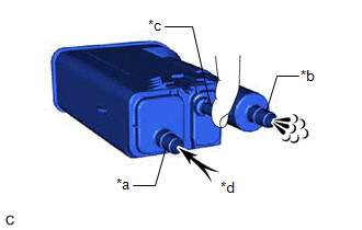
| (2) With the vent line port closed, blow 0.5 kPa (0.005 kgf/cm2, 0.1 psi) of air into the air line port, and check that air flows from the purge line port. If the result is not as specified, replace the canister (charcoal canister assembly). |
|

(c) Check for air leaks.
|
(1) Connect a pressure gauge to the vent line port. |
|
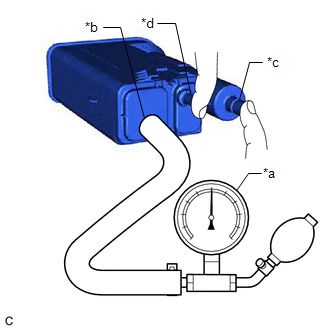
(2) With the purge line port closed, apply 20 kPa (150 mmHg, 5.91 in. Hg) of pressurized air into the vent line port, then confirm that pressure is maintained for 1 minute.
If the result is not as specified, replace the canister (charcoal canister assembly).
2. INSPECT NO. 2 CHARCOAL CANISTER SUB-ASSEMBLY
| (a) Visually check the No. 2 charcoal canister sub-assembly. (1) Visually check the No. 2 charcoal canister sub-assembly for cracks or damage. If cracks or damage are found, replace the No. 2 charcoal canister sub-assembly. |
|
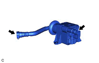
(b) Check No. 2 charcoal canister sub-assembly operation.
| (1) Blow 0.5 kPa (0.005 kgf/cm2, 0.1 psi) of air into the port A, and check that air flows from the port B. If the result is not as specified, replace the No. 2 charcoal canister sub-assembly. |
|
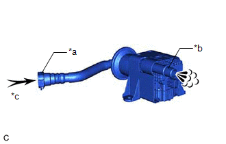
(c) Check for air leaks.
|
(1) Connect a pressure gauge to the port A. |
|
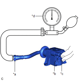
(2) With the port B and leak detection pump sub-assembly connector closed, apply 20 kPa (150 mmHg, 5.91 in. Hg) of pressurized air into the port A, then confirm that pressure is maintained for 1 minute.
If the result is not as specified, replace the No. 2 charcoal canister sub-assembly.
(d) Check the leak detection pump sub-assembly.
| (1) Connect a positive (+) lead from the battery to terminal 5 and a negative (-) lead to terminal 1. |
|
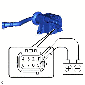
(2) Check that a clicking sound is heard from the leak detection pump sub-assembly.
If the result is not as specified, replace the leak detection pump sub-assembly.
READ NEXT:
 Installation
INSTALLATION PROCEDURE 1. INSTALL LEAK DETECTION PUMP SUB-ASSEMBLY
HINT: Only perform this procedure when replacement of the leak detection pump sub-assembly is necessary.
(a) Engage the 2 cla
Parts Location
PARTS LOCATION ILLUSTRATION
*1 CANISTER (CHARCOAL CANISTER ASSEMBLY)
*2 FUEL TANK CAP ASSEMBLY
*3 PCV VALVE (VENTILATION VALVE SUB-ASSEMBLY)
*4 PURGE VALVE (PURGE
SEE MORE:
Readiness Monitor Drive Pattern
READINESS MONITOR DRIVE PATTERN PURPOSE OF READINESS TESTS
The On-Board Diagnostic (OBD II) system is designed to monitor the performance of emission related components, and indicate any detected abnormalities using DTCs (Diagnostic Trouble Codes). Since various components need to be monitored
Fail-safe Chart
FAIL-SAFE CHART FAIL-SAFE FUNCTION (a) When communication fails in any of the CAN bus lines (communication lines), a fail-safe function(s) will operate. The fail-safe function that is specified for each system operates to prevent those systems from malfunctioning.
(b) The following table shows the
