Toyota Camry (XV70): Parts Location
PARTS LOCATION
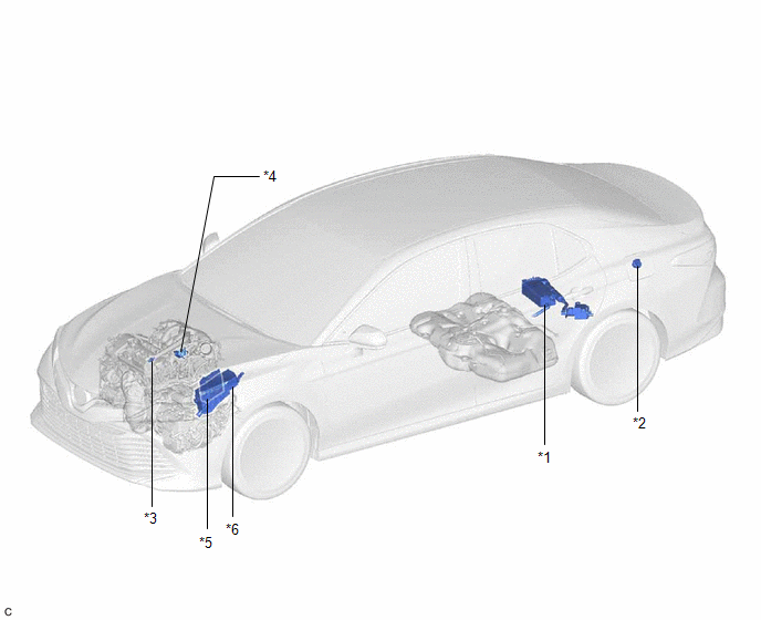
ILLUSTRATION
|
*1 | CANISTER (CHARCOAL CANISTER ASSEMBLY) |
*2 | FUEL TANK CAP ASSEMBLY |
|
*3 | PCV VALVE (VENTILATION VALVE SUB-ASSEMBLY) |
*4 | PURGE VALVE (PURGE VSV) |
|
*5 | ECM |
*6 | ENGINE ROOM RELAY BLOCK AND JUNCTION BLOCK ASSEMBLY - EFI-MAIN NO. 1 RELAY - EFI-MAIN NO. 1 FUSE |
READ NEXT:
 System Diagram
SYSTEM DIAGRAM
*1 Purge Valve (Purge VSV)
*2 Fuel Tank Cap Assembly
*3 Fuel Tank Assembly
*4 Canister Filter
*5 Fuel Cut-off Valve
*6 ECM
On-vehicle Inspection
ON-VEHICLE INSPECTION PROCEDURE
1. INSPECT FUEL CUT OPERATION (a) Start the engine. (b) Warm up the engine.
(c) Increase the engine speed to approximately 3500 rpm. (d) Use a sound scope to check
Fuel Tank Cap
InspectionINSPECTION PROCEDURE
1. INSPECT FUEL TANK CAP ASSEMBLY
(a) Visually check that the fuel tank cap assembly and gasket are not deformed or damaged.
If the result is not as specified
SEE MORE:
EVAP System
RELATED DTCS
DTC No. SAE
Monitoring Item Link
P00FE00 P00FE
EVAP vent line blocked
P043E00 P043E
Reference orifice clogged (built into canister pump module)
P043F00 P043F
Reference orifice high-flow (built into canister
Voice is not Recognized
PROCEDURE
1. CHECK CONDITION
(a) While paying attention to the condition of the spoken voice command, perform a voice recognition operation.
OK: Voice command is recognized normally.
HINT:
When the voice command is recognized, the content of the voice command is displayed in t
© 2023-2026 Copyright www.tocamry.com
