Toyota Camry (XV70): System Diagram
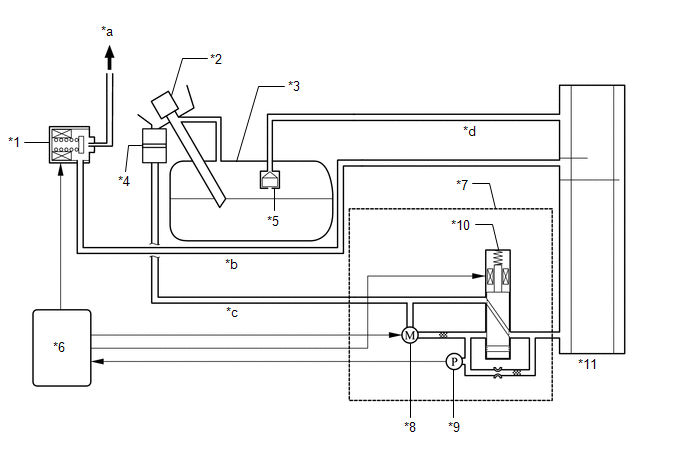
SYSTEM DIAGRAM
|
*1 | Purge Valve (Purge VSV) |
*2 | Fuel Tank Cap Assembly |
|
*3 | Fuel Tank Assembly |
*4 | Canister Filter |
|
*5 | Fuel Cut-off Valve |
*6 | ECM |
|
*7 | Canister Pump Module (Charcoal Canister Leak Detection Pump Sub-assembly) |
*8 | Pump Motor |
|
*9 | Canister Pressure Sensor |
*10 | Vent Valve |
|
*11 | Canister (Charcoal Canister Assembly) |
- | - |
|
*a | to Intake Manifold |
*b | Purge Line |
|
*c | Air Line |
*d | Vent Line |
READ NEXT:
 On-vehicle Inspection
ON-VEHICLE INSPECTION PROCEDURE
1. INSPECT FUEL CUT OPERATION (a) Start the engine. (b) Warm up the engine.
(c) Increase the engine speed to approximately 3500 rpm. (d) Use a sound scope to check
Fuel Tank Cap
InspectionINSPECTION PROCEDURE
1. INSPECT FUEL TANK CAP ASSEMBLY
(a) Visually check that the fuel tank cap assembly and gasket are not deformed or damaged.
If the result is not as specified
Pcv Valve
ComponentsCOMPONENTS ILLUSTRATION
*1 PCV VALVE (VENTILATION VALVE SUB-ASSEMBLY)
*2 V-BANK COVER SUB-ASSEMBLY
*3 VENTILATION HOSE
- -
N*m (kgf*cm, f
SEE MORE:
Rear Power Window LH does not Operate with Rear Power Window Switch LH
DESCRIPTION When the ignition switch is ON, the power window regulator motor assembly (for rear LH door) is operated by the rear power window regulator switch assembly (for LH door). The power window regulator motor assembly (for rear LH door) has motor, regulator, and ECU functions. WIRING DIAGRAM
Right Rear Wheel Speed Sensor Circuit Short to Battery (C051212)
DESCRIPTION Each speed sensor detects wheel speed and sends signals to the skid control ECU (brake actuator assembly). These signals are used by the ABS control.
The speed sensor detects the magnetic fields of the speed sensor rotor as it rotates and outputs a pulse signal.
The frequency of the
© 2023-2026 Copyright www.tocamry.com
