Toyota Camry (XV70): Removal
REMOVAL
CAUTION / NOTICE / HINT
NOTICE:
- Immediately after installing the brake pads, the braking performance may be reduced. Always perform a road test in a safe place while paying attention to the surroundings.
- After replacing the rear disc brake pads, the brake pedal may feel soft due to clearance between the rear disc brake pads and rear disc. Depress the brake pedal several times until the brake pedal feels firm.
- After replacing the rear disc brake pads, always perform a road test to check the braking performance and check for vibrations.
HINT:
- Use the same procedure for the RH side and LH side.
- The following procedure is for the LH side.
PROCEDURE
1. REMOVE REAR WHEEL
Click here .gif)
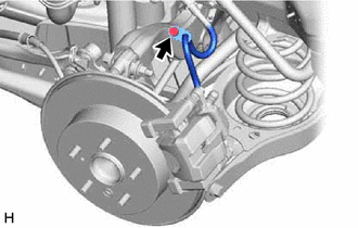
2. SEPARATE REAR FLEXIBLE HOSE
| (a) Remove the bolt and separate the rear flexible hose from the rear flexible hose bracket. |
|
3. REMOVE REAR DISC BRAKE PAD
CAUTION:
- Be careful not to get pinched by the rear disc brake cylinder assembly or other parts when removing the rear disc brake pads.
- After lifting up the rear disc brake cylinder assembly, secure it in place before performing any work on it.
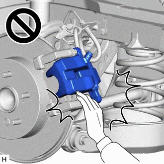
- The rear disc brake cylinder assembly could fall, pinching hands or fingers and causing injury.
| (a) Hold the rear disc brake cylinder slide pin (lower side) and remove the bolt. |
|
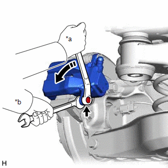
(b) Pull the rear disc brake cylinder assembly upward.
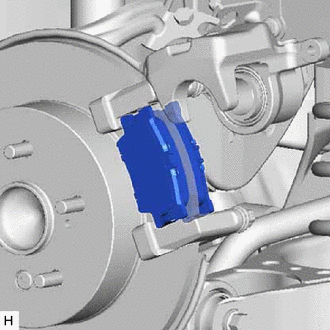
| (c) Remove the 2 rear disc brake pads from the rear disc brake cylinder mounting. |
|
4. REMOVE REAR DISC BRAKE ANTI-SQUEAL SHIM KIT
(a) Remove the rear No. 1 disc brake anti-squeal shim from each rear disc brake pad.
| (b) Using a screwdriver, remove the rear disc brake pad wear indicator plate from each rear disc brake pad. |
|
.png)
READ NEXT:
 Installation
INSTALLATION CAUTION / NOTICE / HINT
NOTICE:
Immediately after installing the brake pads, the braking performance may be reduced. Always perform a road test in a safe place while paying attentio
Rear Side Marker Light Bulb
ComponentsCOMPONENTS ILLUSTRATION
*1 REAR COMBINATION LIGHT ASSEMBLY
*2 REAR COMBINATION LIGHT COVER
*3 REAR SIDE MARKER LIGHT BULB
- - RemovalREMOVAL CAUTION
Rear Turn Signal Light Bulb
ComponentsCOMPONENTS ILLUSTRATION
*1 REAR COMBINATION LIGHT ASSEMBLY
*2 REAR COMBINATION LIGHT COVER
*3 REAR TURN SIGNAL LIGHT BULB
- - RemovalREMOVAL CAUTION
SEE MORE:
Stop Lamp Relay Actuator Stuck Off (C13807F)
DESCRIPTION Refer to DTC C13807E. Click here
DTC No. Detection Item
DTC Detection Condition Trouble Area
C13807F Stop Lamp Relay Actuator Stuck Off
When the voltage at the +BS terminal is between 10 V or more and the stop light control relay (stop light switch asse
Cruise Main Indicator Light Circuit
DESCRIPTION When the dynamic radar cruise control system is turned on using the cruise control main switch, the cruise control indicator (vehicle-to-vehicle distance control mode) illuminates. The ECM uses this and other indicators to indicate the status (presence or absence of a preceding vehicle,
© 2023-2026 Copyright www.tocamry.com
