Toyota Camry (XV70): Rear Side Marker Light Bulb
Components
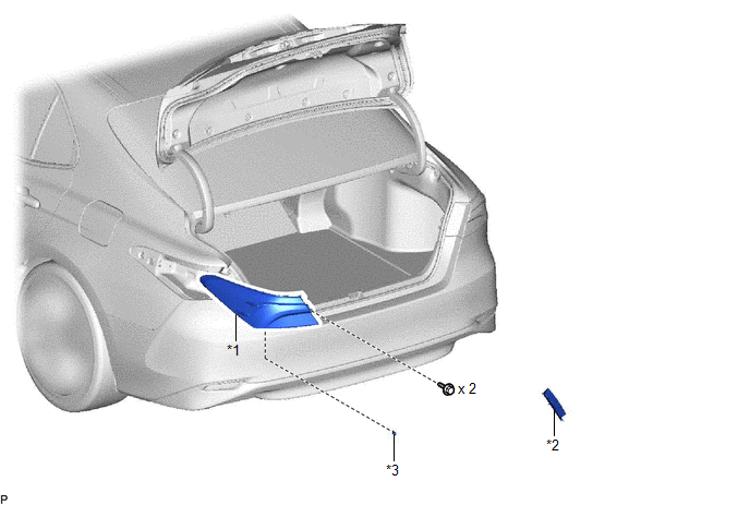
COMPONENTS
ILLUSTRATION
|
*1 | REAR COMBINATION LIGHT ASSEMBLY |
*2 | REAR COMBINATION LIGHT COVER |
|
*3 | REAR SIDE MARKER LIGHT BULB |
- | - |
Removal
REMOVAL
CAUTION / NOTICE / HINT
HINT:
- Use the same procedure for the RH side and LH side.
- The following procedure is for the LH side.
PROCEDURE
1. REMOVE REAR COMBINATION LIGHT COVER
Click here .gif)
2. SEPARATE REAR COMBINATION LIGHT ASSEMBLY
Click here
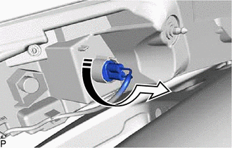
3. REMOVE REAR SIDE MARKER LIGHT BULB
(a) Turn the rear combination light socket and wire with the rear side marker light bulb as shown in the illustration to disconnect them as a unit.
.png) |
Remove in this Direction |
(b) Remove the rear side marker light bulb from the rear combination light socket and wire.
Installation
INSTALLATION
CAUTION / NOTICE / HINT
HINT:
- Use the same procedure for the RH side and LH side.
- The following procedure is for the LH side.
PROCEDURE
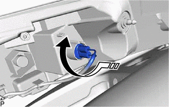
1. INSTALL REAR SIDE MARKER LIGHT BULB
(a) Install the rear side marker light bulb to the rear combination light socket and wire.
(b) Turn the rear combination light socket and wire with the rear side marker light bulb as shown in the illustration to connect them as a unit.
.png) |
Install in this Direction |
2. INSTALL REAR COMBINATION LIGHT ASSEMBLY
Click here .gif)
3. INSTALL REAR COMBINATION LIGHT COVER
Click here
READ NEXT:
 Rear Turn Signal Light Bulb
ComponentsCOMPONENTS ILLUSTRATION
*1 REAR COMBINATION LIGHT ASSEMBLY
*2 REAR COMBINATION LIGHT COVER
*3 REAR TURN SIGNAL LIGHT BULB
- - RemovalREMOVAL CAUTION
Tire And Wheel
ComponentsCOMPONENTS ILLUSTRATION
*A for Steel Wheel
*B except Steel Wheel
*1 WHEEL ASSEMBLY
*2 AXLE HUB NUT
*3 WHEEL CAP
- -
Tig
Transmitter Battery(w/ Smart Key System)
ComponentsCOMPONENTS ILLUSTRATION
*1 TRANSMITTER BATTERY
*2 MECHANICAL KEY
*3 TRANSMITTER HOUSING COVER
*4 TRANSMITTER HOUSING CASE
*5 SMART KEY DOOR CO
SEE MORE:
Diagnostic Trouble Code Chart
DIAGNOSTIC TROUBLE CODE CHART Vehicle Stability Control System
DTC No. Detection Item
Link C00631C
Yaw Rate Sensor Circuit Voltage Out of Range
C00631F Yaw Rate Sensor Circuit Intermittent
C006396 Yaw Rate Sensor Component Internal Failure
Brake System Control Module "A" System Internal Failure (C059704,C059746,C060B49,C061049,C13CF1C,C13D41C)
DESCRIPTION The following DTCs are stored when a malfunction occurs in the skid control ECU (brake actuator assembly).
DTC No. Detection Item
DTC Detection Condition Trouble Area
Memory Note
C059704 Brake System Control Module "A" System Internal Failure
Skid co
