Toyota Camry (XV70): Removal
REMOVAL
PROCEDURE
1. REMOVE FRONT WHEEL RH
Click here .gif)
2. REMOVE FRONT FENDER APRON SEAL RH
Click here
3. REMOVE V-BANK COVER SUB-ASSEMBLY
Click here
4. REMOVE CAMSHAFT TIMING OIL CONTROL SOLENOID ASSEMBLY (for Exhaust Side of Bank 1)
Click here
5. SET NO. 1 CYLINDER TO TDC/COMPRESSION
| (a) Turn the crankshaft pulley clockwise until its timing mark (cutout) is aligned with the timing mark on the timing chain cover assembly as shown in the illustration. |
|
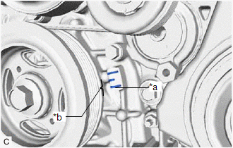
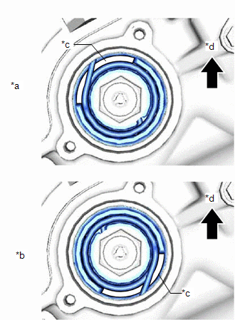
| (b) Check that the cutout of the camshaft timing gear assembly is at the top. HINT: If the cutout of the camshaft timing gear assembly is not at the top, turn the crankshaft 360° clockwise and align the timing mark (cutout) of the crankshaft pulley with the timing mark on the timing chain cover assembly again. |
|
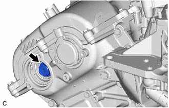
6. REMOVE CAMSHAFT TIMING GEAR BOLT
| (a) While holding the crankshaft pulley, remove the camshaft timing gear bolt. NOTICE:
|
|
READ NEXT:
 Inspection
INSPECTION PROCEDURE 1. INSPECT CAMSHAFT TIMING GEAR BOLT
(a) Check the stroke of the plunger in the center of the camshaft timing gear bolt.
Standard Stroke: 2.2 mm (0.0866 in.) or more HIN
Installation
INSTALLATION PROCEDURE 1. INSTALL CAMSHAFT TIMING GEAR BOLT
(a) Make sure that the No. 1 cylinder is at TDC/compression. HINT:
Check that the cutout of the camshaft timing gear assembly is at the
SEE MORE:
Lost Communication with Cruise Control Front Distance Range Sensor Signal Sensor or Center Missing Message (U023587)
DESCRIPTION The forward recognition camera and millimeter wave radar sensor assembly communicate via CAN communication. If there is an error in the communication with the millimeter wave radar sensor assembly, the forward recognition camera stores DTC U023587.
DTC No. Detection Item
D
Components
COMPONENTS ILLUSTRATION
*1 LUGGAGE COMPARTMENT DOOR EMBLEM
*2 NO. 2 LUGGAGE COMPARTMENT DOOR NAME PLATE
● Non-reusable part
- - ILLUSTRATION
*1 NO. 3 LUGGAGE COMPARTMENT DOOR PLATE
- -
● Non-reusable part
