Toyota Camry (XV70): Removal
REMOVAL
PROCEDURE
1. REMOVE V-BANK COVER SUB-ASSEMBLY
Click here .gif)
2. REMOVE CAMSHAFT TIMING OIL CONTROL SOLENOID ASSEMBLY (for Exhaust Side of Bank 2)
| (a) Disconnect the camshaft timing oil control solenoid assembly connector. |
|
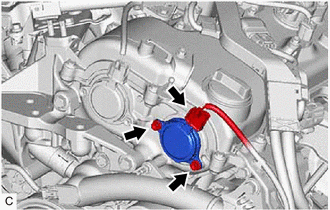
(b) Remove the 2 bolts and camshaft timing oil control solenoid assembly from the timing chain cover assembly.
NOTICE:
If the camshaft timing oil control solenoid assembly has been struck or dropped, replace it.
(c) Remove the O-ring from the camshaft timing oil control solenoid assembly.
NOTICE:
- If the O-ring comes off in the timing chain cover assembly, make sure to remove it.
- Do not drop the O-ring into the timing chain cover assembly.
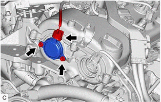
3. REMOVE CAMSHAFT TIMING OIL CONTROL SOLENOID ASSEMBLY (for Intake Side of Bank 1)
| (a) Disconnect the camshaft timing oil control solenoid assembly connector. |
|
(b) Disengage the clamp to disconnect the engine wire.
(c) Remove the 2 bolts and camshaft timing oil control solenoid assembly from the timing chain cover assembly.
NOTICE:
If the camshaft timing oil control solenoid assembly has been struck or dropped, replace it.
(d) Remove the O-ring from the camshaft timing oil control solenoid assembly.
NOTICE:
- If the O-ring comes off in the timing chain cover assembly, make sure to remove it.
- Do not drop the O-ring into the timing chain cover assembly.
4. REMOVE FRONT FENDER APRON SEAL RH
Click here
5. REMOVE CAMSHAFT TIMING OIL CONTROL SOLENOID ASSEMBLY (for Exhaust Side of Bank 1)
| (a) Disconnect the camshaft timing oil control solenoid assembly connector. |
|
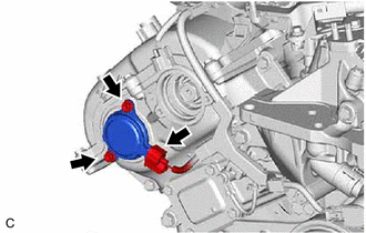
(b) Remove the 2 bolts and camshaft timing oil control solenoid assembly from the timing chain cover assembly.
NOTICE:
If the camshaft timing oil control solenoid assembly has been struck or dropped, replace it.
(c) Remove the O-ring from the camshaft timing oil control solenoid assembly.
NOTICE:
- If the O-ring comes off in the timing chain cover assembly, make sure to remove it.
- Do not drop the O-ring into the timing chain cover assembly.
6. REMOVE ENGINE ASSEMBLY WITH TRANSAXLE
Click here
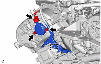
7. REMOVE CAMSHAFT TIMING OIL CONTROL SOLENOID ASSEMBLY (for Intake Side of Bank 2)
| (a) Disconnect the camshaft timing oil control solenoid assembly connector. |
|
(b) Remove the 2 bolts and camshaft timing oil control solenoid assembly from the timing chain cover assembly.
NOTICE:
If the camshaft timing oil control solenoid assembly has been struck or dropped, replace it.
(c) Remove the O-ring from the camshaft timing oil control solenoid assembly.
NOTICE:
- If the O-ring comes off in the timing chain cover assembly, make sure to remove it.
- Do not drop the O-ring into the timing chain cover assembly.
READ NEXT:
 Inspection
INSPECTION PROCEDURE 1. INSPECT CAMSHAFT TIMING OIL CONTROL SOLENOID ASSEMBLY
HINT: Use the same procedure for the intake side and exhaust side.
(a) Check the resistance.
(1) Measure the res
Installation
INSTALLATION PROCEDURE 1. INSTALL CAMSHAFT TIMING OIL CONTROL SOLENOID ASSEMBLY (for Intake Side of Bank 2)
(a) Apply engine oil to a new O-ring and install it to the camshaft timing oil control
SEE MORE:
On-vehicle Inspection
ON-VEHICLE INSPECTION PROCEDURE
1. CONNECT TECHSTREAM (a) Connect the Techstream to the DLC3 with the ignition switch off.
(b) Start the engine and run it at idle. (c) Turn the Techstream on.
(d) Enter the following menus: Chassis / Brake / Active Test. HINT:
Refer to the Techstream operator
Brake System Control Module "A" System Voltage System Voltage Low (C137BA2)
DESCRIPTION If a malfunction is detected in the power supply circuit, the skid control ECU (brake actuator assembly) stores this DTC and the fail-safe function prohibits ABS operation.
This DTC is stored when the +BS terminal voltage meets one of the DTC detection conditions due to a malfunction i
