Toyota Camry (XV70): Short to +B in Outer Mirror Indicator(Master) (C1AB0)
DESCRIPTION
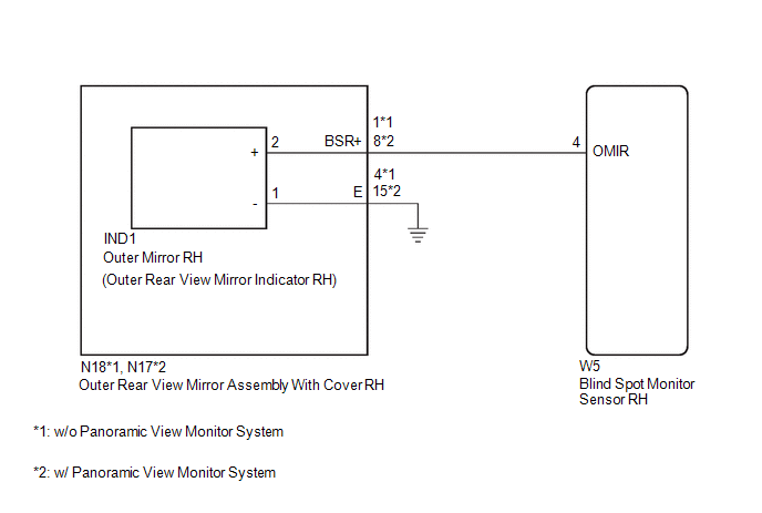
This DTC is stored when the blind spot monitor sensor RH detects a short to +B in the outer rear view mirror indicator RH.
|
DTC No. | Detection Item |
DTC Detection Condition | Trouble Area |
|---|---|---|---|
|
C1AB0 | Short to +B in Outer Mirror Indicator(Master) | Both of the following conditions are met:
|
|
WIRING DIAGRAM
CAUTION / NOTICE / HINT
NOTICE:
When checking for DTCs, make sure that the blind spot monitor system is turned on.
PROCEDURE
| 1. |
CHECK DTC |
(a) Turn the engine switch off.
(b) Turn the engine switch on (IG).
(c) Recheck for DTCs and check if the same DTC is output again.
Body Electrical > Blind Spot Monitor Master > Trouble CodesOK:
No DTCs are output.
| OK | .gif) |
USE SIMULATION METHOD TO CHECK |
.gif)
|
.gif)
| 2. |
CHECK HARNESS AND CONNECTOR (OUTER REAR VIEW MIRROR INDICATOR CIRCUIT) |
(a) Disconnect the W5 blind spot monitor sensor RH connector.
(b) Measure the voltage according to the value(s) in the table below.
Standard Voltage:
|
Tester Connection | Condition |
Specified Condition |
|---|---|---|
|
W5-4 (OMIR) - Body ground |
Engine switch on (IG) |
Below 1 V |
| OK | | REPLACE BLIND SPOT MONITOR SENSOR RH
|
|
| 3. |
CHECK HARNESS AND CONNECTOR (OUTER REAR VIEW MIRROR INDICATOR CIRCUIT) |
(a) Disconnect the IND1 outer mirror RH connector.
(b) Measure the voltage according to the value(s) in the table below.
Standard Voltage:
|
Tester Connection | Condition |
Specified Condition |
|---|---|---|
|
W5-4 (OMIR) - Body ground |
Engine switch on (IG) |
Below 1 V |
| OK | | REPLACE OUTER MIRROR RH |
|
| 4. |
CHECK HARNESS AND CONNECTOR (OUTER REAR VIEW MIRROR INDICATOR CIRCUIT) |
(a) Disconnect the N18*1 or N17*2 outer rear view mirror assembly with cover RH connector.
(b) Measure the voltage according to the value(s) in the table below.
Standard Voltage:
|
Tester Connection | Condition |
Specified Condition |
|---|---|---|
|
W5-4 (OMIR) - Body ground |
Engine switch on (IG) |
Below 1 V |
- *1: w/o Panoramic View Monitor System
- *2: w/ Panoramic View Monitor System
| OK | | REPLACE OUTER REAR VIEW MIRROR ASSEMBLY WITH COVER RH
|
| NG | | REPAIR OR REPLACE HARNESS OR CONNECTOR |
READ NEXT:
 Short to +B in Outer Mirror Indicator(Slave) (C1AB1)
DESCRIPTION This DTC is stored when the blind spot monitor sensor LH detects a short to +B in the outer rear view mirror indicator LH.
DTC No. Detection Item
DTC Detection Condition Tro
Short to GND in Outer Mirror Indicator(Master) (C1AB2)
DESCRIPTION This DTC is stored when the blind spot monitor sensor RH detects a short to ground in the outer rear view mirror indicator RH.
DTC No. Detection Item
DTC Detection Condition
Short to GND in Outer Mirror Indicator(Slave) (C1AB3)
DESCRIPTION This DTC is stored when the blind spot monitor sensor LH detects a short to ground in the outer rear view mirror indicator LH.
DTC No. Detection Item
DTC Detection Condition
SEE MORE:
Components
COMPONENTS ILLUSTRATION
*1 CHECK VALVE GROMMET
*2 VACUUM WARNING SWITCH ASSEMBLY
● Non-reusable part
- -
Inspection
INSPECTION PROCEDURE 1. INSPECT BRAKE CYLINDER AND PISTON
(a) Check the front disc brake cylinder bore and front disc brake piston for rust and scoring. If necessary, replace the front disc brake cylinder assembly and front disc brake piston.
2. INSPECT PAD LINING THICKNESS
(a) Using a rul
