Toyota Camry (XV70): Inspection
INSPECTION
PROCEDURE
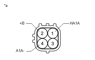
1. INSPECT AIR FUEL RATIO SENSOR (for Bank 1)
| (a) Measure the resistance according to the value(s) in the table below. Standard Resistance:
If the result is not as specified, replace the air fuel ratio sensor. |
|
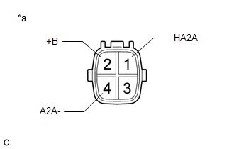
2. INSPECT AIR FUEL RATIO SENSOR (for Bank 2)
| (a) Measure the resistance according to the value(s) in the table below. Standard Resistance:
If the result is not as specified, replace the air fuel ratio sensor. |
|
READ NEXT:
 Installation
INSTALLATION PROCEDURE 1. INSTALL AIR FUEL RATIO SENSOR (for Bank 1)
HINT: Perform "Inspection After Repair" after replacing the air fuel ratio sensor.
Click here
(a) Using SST, instal
Components
COMPONENTS ILLUSTRATION
*1 FRONT FENDER APRON SEAL RH
*2 V-BANK COVER SUB-ASSEMBLY
N*m (kgf*cm, ft.*lbf): Specified torque
- - ILLUSTRATION
*1
SEE MORE:
Software Incompatibility with Body Control Module Invalid/Incompatible Software Component (U032257)
DESCRIPTION The forward recognition camera receives vehicle information from the main body ECU (multiplex network body ECU) via CAN communication.
DTC U032257 is stored when the vehicle information from the main body ECU (multiplex network body ECU) and that stored in the forward recognition camer
Vehicle Speed Signal Circuit between Navigation ECU and Combination Meter
DESCRIPTION The navigation ECU receives a vehicle speed signal from the combination meter assembly.
HINT:
A voltage of 12 V or 5 V is output from each ECU and then input to the combination meter assembly. The signal is changed to a pulse signal at the transistor in the combination meter assemb
