Toyota Camry (XV70): Components
COMPONENTS
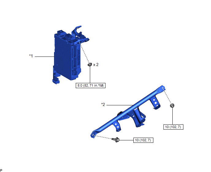
ILLUSTRATION
|
*1 | INSTRUMENT PANEL JUNCTION BLOCK ASSEMBLY WITH MAIN BODY ECU |
*2 | NO. 3 INSTRUMENT PANEL TO COWL BRACE SUB-ASSEMBLY |
.png) |
N*m (kgf*cm, ft.*lbf): Specified torque |
- | - |
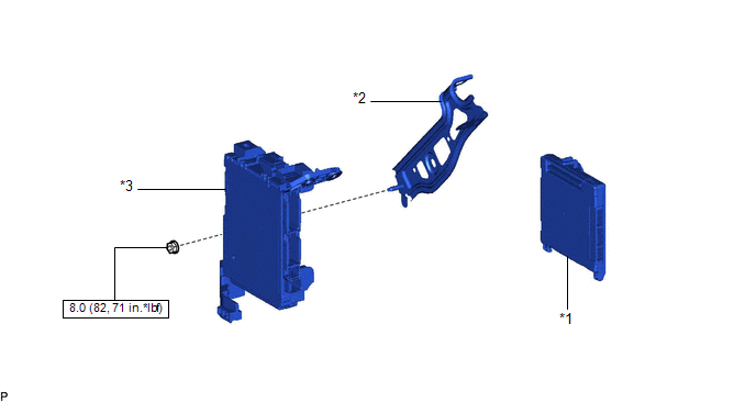
ILLUSTRATION
|
*1 | MAIN BODY ECU (MULTIPLEX NETWORK BODY ECU) |
*2 | WIRING HARNESS CLAMP BRACKET |
|
*3 | INSTRUMENT PANEL JUNCTION BLOCK ASSEMBLY |
- | - |
|
|
N*m (kgf*cm, ft.*lbf): Specified torque |
- | - |
READ NEXT:
 Removal
REMOVAL CAUTION / NOTICE / HINT
The necessary procedures (adjustment, calibration, initialization, or registration) that must be performed after parts are removed and installed, or replaced during m
Installation
INSTALLATION CAUTION / NOTICE / HINT
NOTICE:
Before replacing the main body ECU (multiplex network body ECU), refer to Registration.
w/ Smart Key System: Click here
w/o Smart Key Sys
SEE MORE:
Operation Check
OPERATION CHECK TOYOTA ENTUNE APP SUITE CONNECT RESET PROCEDURE
(a) Duplicate the problem symptom. (b) Check for DTCs and repair the systems for which any DTCs are output.
Click here
(c) Check cellular phone compatibility.
(1) Check if the cellular phone/vehicle is compatible (Refer to ht
Front Brake Flexible Hose
ComponentsCOMPONENTS ILLUSTRATION
*1 FRONT FLEXIBLE HOSE
*2 GASKET
*3 BRAKE LINE
*4 FRONT SPEED SENSOR
*5 UNION BOLT
- -
Tightening torque for "Major areas involving basic vehicle performance such as moving/turning/stopping" : N*
© 2023-2026 Copyright www.tocamry.com
