Toyota Camry (XV70): Installation
INSTALLATION
PROCEDURE
1. INSTALL FRONT ENGINE MOUNTING INSULATOR
(a) Install the stay to the front engine mounting insulator with the nut.
Torque:
6.0 N·m {61 kgf·cm, 53 in·lbf}
(b) Install the front engine mounting insulator to the front frame assembly with the 3 nuts.
Torque:
72 N·m {734 kgf·cm, 53 ft·lbf}
| (c) Install the front engine mounting bracket to the transaxle housing with the 3 bolts. Torque: Bolt (A), (B) and (C) : 42 N·m {428 kgf·cm, 31 ft·lbf} NOTICE: Temporarily tighten the bolt (A), and then fully tighten the 3 bolts in the order of (B), (C) and (A). |
|
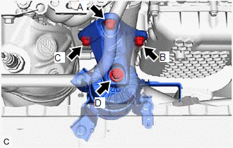
(d) Install the front engine mounting bracket to the front engine mounting insulator with the bolt.
Torque:
Bolt (D) :
72 N·m {734 kgf·cm, 53 ft·lbf}
(e) Connect the vacuum hose to the front engine mounting insulator.
(f) Engage the 2 clamps to install the vacuum hoses to the front engine mounting insulator.
2. INSTALL REAR ENGINE UNDER COVER LH
Click here
.gif)
3. INSTALL NO. 1 ENGINE UNDER COVER
Click here
4. INSTALL FRONT WHEEL OPENING EXTENSION PAD LH
Click here
5. INSTALL FRONT WHEEL OPENING EXTENSION PAD RH
Click here
6. INSTALL V-BANK COVER SUB-ASSEMBLY
Click here
7. INSTALL VACUUM SWITCHING VALVE (for Active Control Engine Mount System)
Click here
READ NEXT:
 Components
COMPONENTS ILLUSTRATION
*1 REAR ENGINE MOUNTING INSULATOR
*2 VACUUM HOSE
*3 WIRE HARNESS CLAMP BRACKET
- -
Tightening torque for "Major areas invol
On-vehicle Inspection
ON-VEHICLE INSPECTION CAUTION / NOTICE / HINT
HINT: Refer to Problem Symptoms Table. Click here
PROCEDURE
1. REMOVE FRONT WHEEL OPENING EXTENSION PAD LH Click here
2. REMOVE FRONT
SEE MORE:
Using the storage
features
List of storage features
Auxiliary boxes
Glove box
Bottle holders/door pockets
Cup holders
Console box
Auxiliary box/open tray
Coin holder
WARNING
Do not leave glasses, spray cans in the storage spaces, as this
may cause the following when cabin temperature becomes high:
Torque Converter Clutch Circuit Short to Ground (P074011)
DESCRIPTION Solenoid (SL) valve is turned on and off by signals from the ECM to control the hydraulic pressure acting on the lock-up relay valve, which then controls operation of the lock-up clutch.
DTC No. Detection Item
DTC Detection Condition Trouble Area
MIL Memory
Not
