Toyota Camry (XV70): Components
COMPONENTS
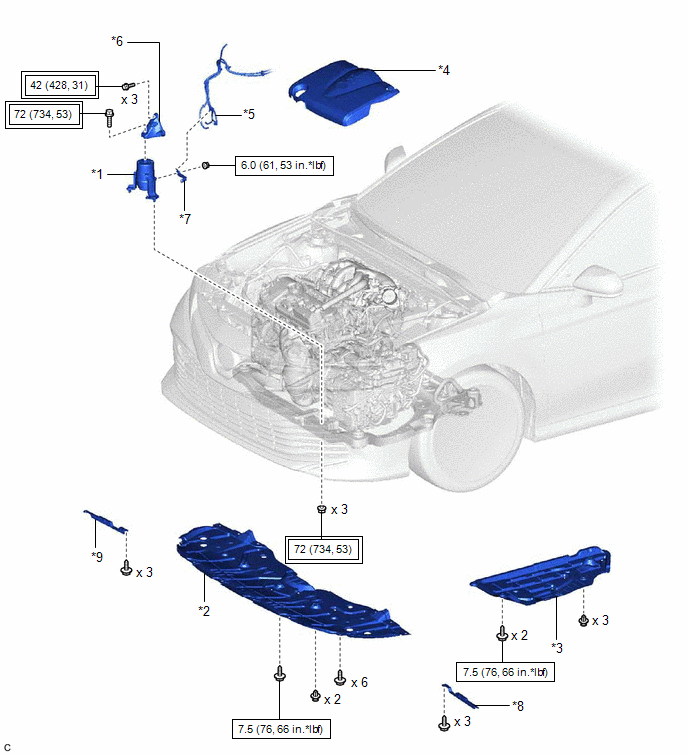
ILLUSTRATION
|
*1 | FRONT ENGINE MOUNTING INSULATOR |
*2 | NO. 1 ENGINE UNDER COVER |
|
*3 | REAR ENGINE UNDER COVER LH |
*4 | V-BANK COVER SUB-ASSEMBLY |
|
*5 | VACUUM HOSE |
*6 | FRONT ENGINE MOUNTING BRACKET |
|
*7 | STAY |
*8 | FRONT WHEEL OPENING EXTENSION PAD LH |
|
*9 | FRONT WHEEL OPENING EXTENSION PAD RH |
- | - |
.png) |
Tightening torque for "Major areas involving basic vehicle performance such as moving/turning/stopping": N*m (kgf*cm, ft.*lbf) |
.png) |
N*m (kgf*cm, ft.*lbf): Specified torque |
READ NEXT:
 On-vehicle Inspection
ON-VEHICLE INSPECTION CAUTION / NOTICE / HINT
HINT: Refer to Problem Symptoms Table. Click here
PROCEDURE
1. REMOVE FRONT WHEEL OPENING EXTENSION PAD LH Click here
2. REMOVE FRONT
Removal
REMOVAL PROCEDURE 1. REMOVE VACUUM SWITCHING VALVE (for Active Control Engine Mount System)
Click here 2. REMOVE V-BANK COVER SUB-ASSEMBLY
Click here
3. REMOVE FRONT WHEEL OPENING EX
Installation
INSTALLATION PROCEDURE 1. INSTALL FRONT ENGINE MOUNTING INSULATOR
(a) Install the stay to the front engine mounting insulator with the nut.
Torque: 6.0 N·m {61 kgf·cm, 53 in·lbf} (b) Install t
SEE MORE:
Cooling Fan Circuit
DESCRIPTION The ECM calculates an appropriate cooling fan speed based on the engine coolant temperature, air conditioning switch status, refrigerant pressure, engine speed and vehicle speed, and sends a signal to the cooling fan ECU (fan with motor assembly). The cooling fan ECU (fan with motor asse
Components
COMPONENTS ILLUSTRATION
*1 NO. 1 INSTRUMENT PANEL UNDER COVER SUB-ASSEMBLY
*2 STOP LIGHT SWITCH ASSEMBLY
© 2023-2026 Copyright www.tocamry.com
