Toyota Camry (XV70): Components
COMPONENTS
ILLUSTRATION
|
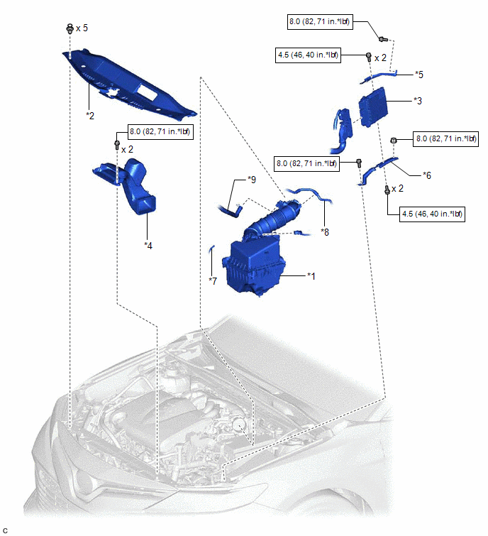
*1 | AIR CLEANER ASSEMBLY WITH AIR CLEANER HOSE |
*2 | COOL AIR INTAKE DUCT SEAL |
|
*3 | ECM |
*4 | INLET AIR CLEANER ASSEMBLY |
|
*5 | NO. 1 ECM BRACKET |
*6 | NO. 2 ECM BRACKET |
|
*7 | VACUUM HOSE |
*8 | NO. 1 FUEL VAPOR FEED HOSE |
|
*9 | NO. 2 VENTILATION HOSE |
- | - |
.png) |
N*m (kgf*cm, ft.*lbf): Specified torque |
- | - |
READ NEXT:
 Removal
REMOVAL CAUTION / NOTICE / HINT
The necessary procedures (adjustment, calibration, initialization or registration) that must be performed after parts are removed and installed, or replaced during EC
Installation
INSTALLATION PROCEDURE 1. INSTALL NO. 2 ECM BRACKET
(a) Install the No. 2 ECM bracket to the ECM with the 2 screws. Torque:
4.5 N·m {46 kgf·cm, 40 in·lbf} 2. INSTALL NO. 1 ECM BRACKET (a) Inst
SEE MORE:
Slave Module Horizontal Axis Misalignment (C1AC2)
DESCRIPTION This DTC is stored when the angle of the blind spot monitor sensor LH deviates more than the allowable range from the horizontal axis.
HINT:
If a drum tester such as a speedometer tester, brake/speedometer combination tester or chassis dynamometer is used with the blind spot monito
Components
COMPONENTS ILLUSTRATION
*1 BATTERY
*2 NEGATIVE BATTERY TERMINAL
*3 POSITIVE BATTERY TERMINAL
*4 NO. 2 BATTERY CLAMP
*5 BATTERY TERMINAL CAP
- -
Tightening torque for "Major areas involving basic vehicle performance such as moving
© 2023-2026 Copyright www.tocamry.com
