Toyota Camry (XV70): Components
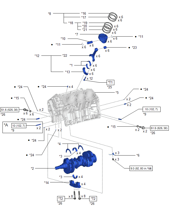
COMPONENTS
ILLUSTRATION
|
*A | w/ Stud Bolt |
- | - |
|
*1 | CONNECTING ROD BEARING |
*2 | CRANKSHAFT |
|
*3 | CRANKSHAFT BEARING |
*4 | CRANKSHAFT THRUST WASHER SET |
|
*5 | CYLINDER BLOCK SUB-ASSEMBLY |
*6 | NO. 1 OIL NOZZLE SUB-ASSEMBLY |
|
*7 | PISTON |
*8 | PISTON RING SET |
|
*9 | STUD BOLT |
*10 | PISTON PIN |
|
*11 | PISTON PIN HOLE SNAP RING |
*12 | CONNECTING ROD SUB-ASSEMBLY |
|
*13 | CONNECTING ROD CAP |
*14 | CRANKSHAFT BEARING CAP |
|
*15 | SEAL WASHER |
*16 | NO. 1 COMPRESSION RING |
|
*17 | NO. 2 COMPRESSION RING |
*18 | OIL RING |
|
*19 | UPPER SIDE RAIL |
*20 | OIL RING EXPANDER |
|
*21 | LOWER SIDE RAIL |
*22 | CONNECTING ROD |
|
*23 | CONNECTING ROD SMALL END BUSH |
*24 | STRAIGHT PIN |
|
*25 | CONNECTING ROD BOLT |
*26 | CRANKSHAFT BEARING CAP SET BOLT |
.png) |
N*m (kgf*cm, ft.*lbf): Specified torque |
● | Non-reusable part |
|
*T1 | 1st: 24.5 (250, 18) 2nd: Turn 90° | *T2 |
1st: 61 (622, 45) 2nd: Turn 90° |
READ NEXT:
 Disassembly
DISASSEMBLY CAUTION / NOTICE / HINT
The necessary procedures (adjustment, calibration, initialization, or registration) that must be performed after parts are removed and installed, or replaced duri
Inspection
INSPECTION PROCEDURE 1. INSPECT CONNECTING ROD THRUST CLEARANCE
(a) Install the connecting rod cap. Click here
(b) Using a dial indicator, measure the thrust clearance while moving the co
Replacement
REPLACEMENT PROCEDURE 1. REPLACE STRAIGHT PIN
NOTICE: If a straight pin is deformed, replace it. (a) Using a plastic hammer, tap in new straight pins to the cylinder block sub-assembly.
*
SEE MORE:
Precaution
PRECAUTION PRECAUTION FOR DISCONNECTING CABLE FROM NEGATIVE BATTERY TERMINAL
NOTICE: When disconnecting the cable from the negative (-) battery terminal, initialize the following systems after the cable is reconnected.
System Name See Procedure
Lane Tracing Assist System
Removal
REMOVAL CAUTION / NOTICE / HINT
The necessary procedures (adjustment, calibration, initialization, or registration) that must be performed after parts are removed, installed, or replaced during automatic transaxle assembly removal/installation are shown below. Necessary Procedure After Parts Remov
© 2023-2026 Copyright www.tocamry.com
