Toyota Camry (XV70): Disassembly
DISASSEMBLY
CAUTION / NOTICE / HINT
The necessary procedures (adjustment, calibration, initialization, or registration) that must be performed after parts are removed and installed, or replaced during engine unit removal/installation are shown below.
Necessary Procedure After Parts Removed/Installed/Replaced|
Replaced Part or Performed Procedure |
Necessary Procedure | Effect/Inoperative Function when Necessary Procedure not Performed |
Link |
|---|---|---|---|
| *1: When the ECM is replaced with a new one, reset memory is unnecessary. | |||
| Battery terminal is disconnected/reconnected |
Perform steering sensor zero point calibration |
Lane Tracing Assist System |
|
|
Pre-collision System | |||
|
Memorize steering angle neutral point |
Parking Assist Monitor System |
| |
|
Panoramic view monitor system |
| ||
|
Replacement of ECM | Vehicle Identification Number (VIN) registration |
MIL comes on |
|
|
ECU communication ID registration (Immobiliser system) |
Engine start function |
| |
| Inspection After Repair |
|
|
|
Replacement of automatic transaxle assembly |
|
|
|
|
Replacement of ECM (If possible, read the transaxle compensation code from the previous ECM) |
| ||
| Replacement of ECM (If impossible, read the transaxle compensation code from the previous ECM) |
| ||
| Replacement of ECM |
Code registration |
|
|
|
Replacement of automatic transaxle fluid |
ATF thermal degradation estimate reset |
The value of the Data List item "ATF Thermal Degradation Estimate" is not estimated correctly. |
|
|
Suspension, tires, etc. (The vehicle height changes because of suspension or tire replacement) |
Rear television camera assembly optical axis (Back camera position setting) |
Parking assist monitor system |
|
|
Replacement of front bumper assembly |
Front television camera view adjustment |
Panoramic view monitor system |
|
|
Suspension, tires, etc. (The vehicle height changes because of suspension or tire replacement) |
| ||
| Front wheel alignment adjustment |
|
|
|
.gif)
PROCEDURE
1. REMOVE PISTON SUB-ASSEMBLY WITH CONNECTING ROD
(a) Check that the matchmarks on the connecting rod sub-assembly and connecting rod cap are aligned.
HINT:
The matchmarks on the connecting rod sub-assembly and connecting rod cap are guides for correct reassembly.
(b) Remove the 2 connecting rod bolts.
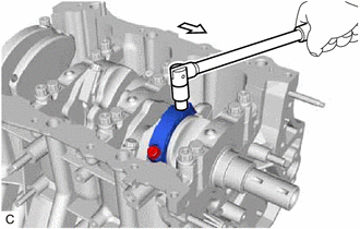
.png) |
Front of Engine |
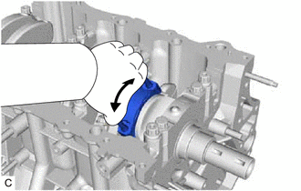
| (c) Using the 2 removed connecting rod bolts, remove the connecting rod cap and lower connecting rod bearing by wiggling the connecting rod cap right and left. HINT: Keep the lower connecting rod bearing installed to the connecting rod cap. |
|
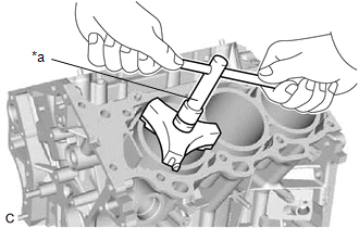
| (d) Using a ridge reamer, remove all of the carbon from the top of the cylinder. |
|
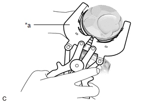
(e) Push the piston, connecting rod sub-assembly and upper connecting rod bearing through the top of the cylinder block sub-assembly.
HINT:
- Keep the connecting rod bearing, connecting rod sub-assembly and connecting rod cap together.
- Arrange the removed parts in such a way that they can be reinstalled to their original locations.
2. REMOVE CONNECTING ROD BEARING
(a) Remove the connecting rod bearings from the connecting rod sub-assembly and connecting rod cap.
HINT:
Arrange the removed parts in such a way that they can be reinstalled to their original locations.
3. REMOVE PISTON RING SET
| (a) Using a piston ring expander, remove the No. 1 compression ring and No. 2 compression ring. |
|
(b) Remove the oil ring expander and 2 side rails by hand.
HINT:
Arrange the removed parts in such a way that they can be reinstalled to their original locations.
4. REMOVE PISTON
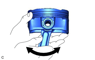
| (a) Check the fitting condition between the piston and piston pin. (1) Try to move the piston back and forth on the piston pin. HINT: If abnormal movement is felt, replace the piston and piston pin as a set. |
|
(b) Remove the connecting rod sub-assembly from the piston.
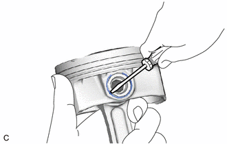
(1) Using a screwdriver, pry out the piston pin hole snap ring (front side).
NOTICE:
- Do not remove the piston pin hole snap ring (rear side) unless it has to be replaced.
- Be careful not to damage the piston when removing the piston pin hole snap ring (rear side).
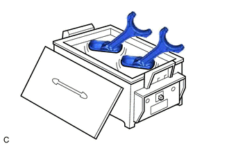
| (2) Gradually heat the piston to approximately 80°C (176°F). CAUTION: Be sure to wear protective gloves. |
|
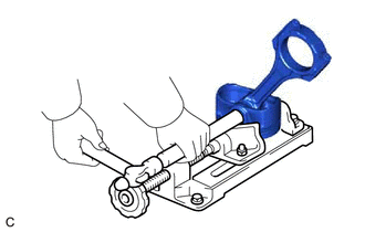
| (3) Using a brass bar and a hammer, lightly tap out the piston pin and remove the connecting rod sub-assembly. HINT:
|
|
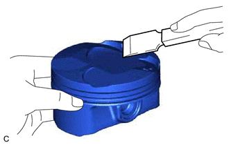
| (c) Using a gasket scraper, remove any carbon from the piston top. NOTICE: Be careful not to scratch the piston. |
|
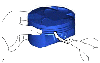
| (d) Using a groove cleaning tool or a broken ring, clean the piston ring grooves. |
|
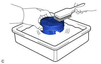
| (e) Using solvent and a brush, thoroughly clean the piston. NOTICE: Do not use a wire brush. |
|
5. REMOVE CRANKSHAFT
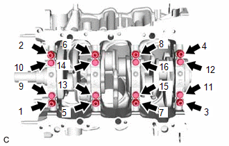
| (a) Uniformly loosen and remove the 8 crankshaft bearing cap set bolts and 8 seal washers in several steps in the order shown in the illustration. |
|
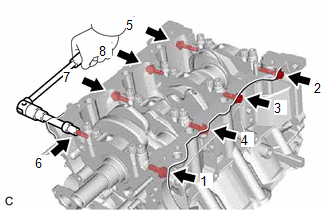
| (b) Uniformly loosen the 16 crankshaft bearing cap set bolts in several steps in the order shown in the illustration. |
|
| (c) Using a screwdriver with its tip wrapped with protective tape, pry out the crankshaft bearing caps. Remove the 4 crankshaft bearing caps and 4 lower crankshaft bearings as a set. NOTICE:
|
|
(d) Remove the crankshaft.
6. REMOVE CRANKSHAFT BEARING
(a) Remove the upper crankshaft bearings and lower crankshaft bearings.
HINT:
Arrange the removed parts in such a way that they can be reinstalled to their original locations.
7. REMOVE CRANKSHAFT THRUST WASHER SET
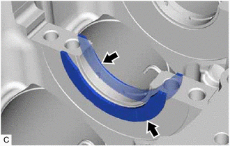
| (a) Remove the crankshaft thrust washer set from the cylinder block sub-assembly. |
|
8. REMOVE NO. 1 OIL NOZZLE SUB-ASSEMBLY
| (a) Using a 5 mm hexagon socket wrench, remove the 3 bolts and 3 No. 1 oil nozzle sub-assemblies. |
|
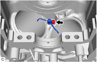
(b) Check the 3 No. 1 oil nozzle sub-assemblies for damage or clogging.
HINT:
If there is damage or clogs, replace the No. 1 oil nozzle sub-assembly.
READ NEXT:
 Inspection
INSPECTION PROCEDURE 1. INSPECT CONNECTING ROD THRUST CLEARANCE
(a) Install the connecting rod cap. Click here
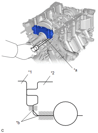
(b) Using a dial indicator, measure the thrust clearance while moving the co
Replacement
REPLACEMENT PROCEDURE 1. REPLACE STRAIGHT PIN
NOTICE: If a straight pin is deformed, replace it. (a) Using a plastic hammer, tap in new straight pins to the cylinder block sub-assembly.
*
Reassembly
REASSEMBLY PROCEDURE 1. INSTALL NO. 1 OIL NOZZLE SUB-ASSEMBLY
(a) Using a 5 mm hexagon socket wrench, install the 3 No. 1 oil nozzle sub-assemblies to the cylinder block sub-assembly with the 3
SEE MORE:
Pressure Control Solenoid "H" Circuit Short to Battery (P281612)
DESCRIPTION Changing gears is performed by the ECM turning the solenoid (SL1, SL2, SL3, SL4, SL5 and SL6) valves on and off.
If an open or short occurs in any of the solenoid valve circuits, the ECM controls the remaining normal solenoid valves to allow the vehicle to be driven. If all of the sole
Components
COMPONENTS ILLUSTRATION
*1 TRANSMISSION VALVE BODY ASSEMBLY
*2 TRANSAXLE CASE GASKET
*3 NO. 1 FRONT OIL PUMP COVER GASKET
*4 NO. 2 FRONT OIL PUMP COVER GASKET
Tightening torque for "Major areas involving basic vehicle performance such as moving/tu
