Toyota Camry (XV70): Reassembly
REASSEMBLY
PROCEDURE
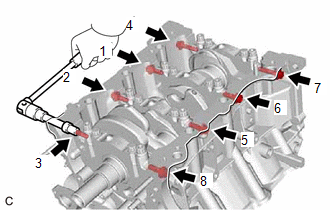
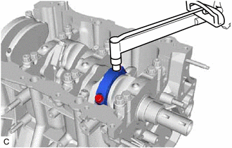
1. INSTALL NO. 1 OIL NOZZLE SUB-ASSEMBLY
| (a) Using a 5 mm hexagon socket wrench, install the 3 No. 1 oil nozzle sub-assemblies to the cylinder block sub-assembly with the 3 bolts. Torque: 9.0 N·m {92 kgf·cm, 80 in·lbf} |
|
.png)
2. INSTALL PISTON
HINT:
Perform this procedure only when replacement of the piston pin hole snap ring (rear side) is necessary.
(a) Using a screwdriver, install a new piston pin hole snap ring (rear side) at one end of the piston pin hole.
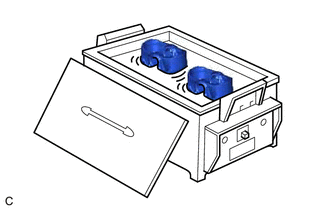
| (b) Gradually heat the piston to approximately 80°C (176°F). |
|
(c) Coat the piston pin with engine oil.
CAUTION:
Be sure to wear protective gloves.
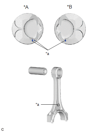
| (d) Align the front marks of the piston and connecting rod sub-assembly, and push in the piston pin with your thumb. HINT: The piston and piston pin are a matched set. |
|
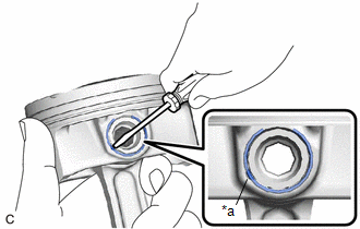
| (e) Using a screwdriver, install a new piston pin hole snap ring at the other end of the piston pin hole. NOTICE: Make sure that the end gap of the piston pin hole snap ring is not aligned with the cutout of the piston pin hole. |
|
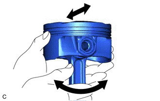
| (f) Check the fitting condition between the piston and piston pin. (1) Move the connecting rod back and forth on the piston pin. Check the fitting condition. HINT: If abnormal movement is felt, replace the piston and piston pin as a set. (2) Rotate the piston back and forth on the piston pin. Check the fitting condition. HINT:
|
|
3. INSTALL PISTON RING SET
(a) Install the oil ring expander and 2 side rails by hand.
| (b) Using a piston ring expander, install the No. 1 compression ring and No. 2 compression ring as shown in the illustration. NOTICE:
|
|
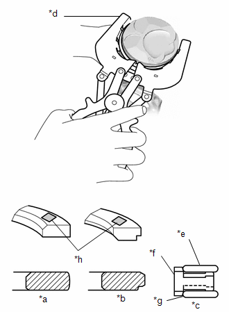
| (c) Position the piston ring set so that the ring ends are as shown in the illustration. NOTICE: Do not align the ring ends. HINT: Perform Inspection After Repair after replacing the piston ring. Click here |
|
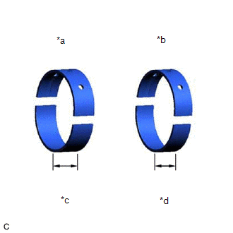
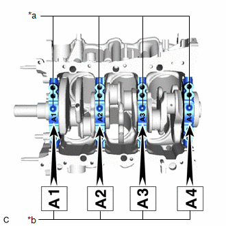
4. INSTALL CRANKSHAFT BEARING
| (a) Clean the main journals and both surfaces of the crankshaft bearings. NOTICE: Crankshaft bearings come in widths of 17.9 mm (0.705 in.) and 20.9 mm (0.823 in.). Install the 20.9 mm (0.823 in.) crankshaft bearings to the No. 1 and No. 4 cylinder block journal positions. Install the 17.9 mm (0.705 in.) crankshaft bearings to the No. 2 and No. 3 positions. |
|
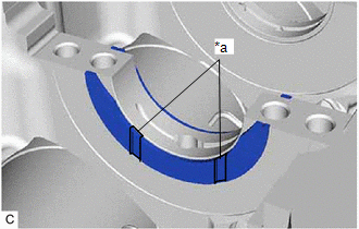
| (b) Install the upper crankshaft bearings. (1) Install the upper crankshaft bearings to the cylinder block sub-assembly as shown in the illustration. NOTICE:
|
|
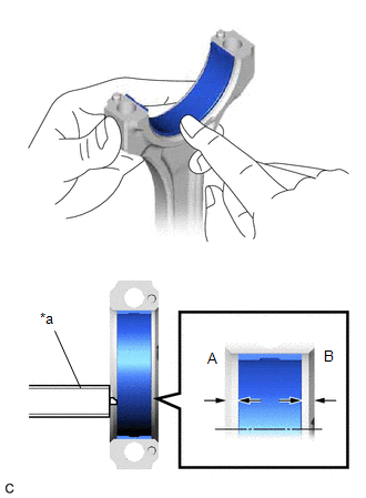
| (c) Install the lower crankshaft bearings. (1) Install the lower crankshaft bearings to the crankshaft bearing caps. (2) Using a vernier caliper, measure the distance between the crankshaft bearing cap edge and lower crankshaft bearing edge. Difference Between (A) and (B): 0.7 mm (0.0276 in.) or less NOTICE:
|
|
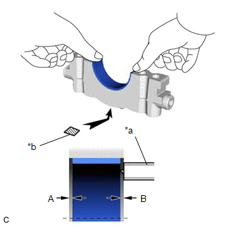
5. INSTALL CRANKSHAFT THRUST WASHER SET
(a) Apply engine oil to the crankshaft thrust washer set.
| (b) Install the crankshaft thrust washer set under the No. 2 journal position of the cylinder block sub-assembly with the oil grooves facing outward. |
|
6. INSTALL CRANKSHAFT
(a) Apply engine oil to the crankshaft bearings, then place the crankshaft on the cylinder block sub-assembly.
| (b) Confirm the projections and numbers of the crankshaft bearing caps and install the 4 crankshaft bearing caps to the cylinder block sub-assembly. HINT: A number is marked on each crankshaft bearing cap to indicate its installation position. |
|
(c) Apply a light coat of engine oil to the threads and under the heads of the crankshaft bearing cap set bolts.
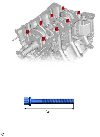
| (d) Temporarily install the 8 crankshaft bearing cap set bolts to the inside positions. Bolt Length: 100 to 102 mm (3.94 to 4.02 in.) |
|
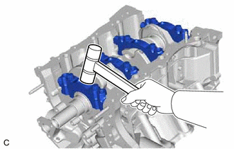
(e) Push the crankshaft bearing cap with your hand until the clearance between the crankshaft bearing cap and the cylinder block sub-assembly is less than 6 mm (0.236 in.) by using the 2 inside crankshaft bearing cap set bolts as a guide.
| (f) Using a plastic hammer, lightly tap the crankshaft bearing cap to ensure a proper fit. |
|
(g) Apply a light coat of engine oil to the threads and under the heads of the 8 crankshaft bearing cap set bolts.
| (h) Temporarily install the 8 crankshaft bearing cap set bolts to the outside positions. Bolt Length: 105.5 to 107.5 mm (4.15 to 4.23 in.) |
|
(i) Install the crankshaft bearing cap set bolts.
HINT:
The crankshaft bearing cap set bolts are tightened in 2 progressive steps.
(j) Step 1:
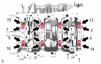
| (1) Uniformly tighten the 16 crankshaft bearing cap set bolts in several steps in the order shown in the illustration. Torque: 61 N·m {622 kgf·cm, 45 ft·lbf} HINT: If a crankshaft bearing cap bolt cannot be tightened to the specified torque, replace it. |
|
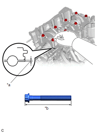
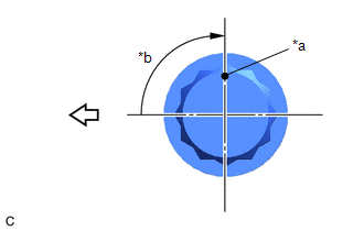
(k) Step 2:
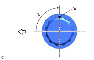
(1) Mark the front of the crankshaft bearing cap set bolts with paint.
|
*a | Paint Mark |
|
*b | Turn 90° |
.png) |
Front of Engine |
(2) Tighten the crankshaft bearing cap set bolts 90° in the order shown in the illustration.
(3) Check that the paint marks are now at a 90° angle to the front.
| (l) Install 8 new seal washers and uniformly tighten the 8 crankshaft bearing cap set bolts in several steps in the order shown in the illustration. Torque: 51.5 N·m {525 kgf·cm, 38 ft·lbf} |
|
(m) Check that the crankshaft turns smoothly.
(n) Check the crankshaft thrust clearance.
Click here .gif)
7. INSTALL CONNECTING ROD BEARING
(a) Install the connecting rod bearings to the connecting rod sub-assembly and connecting rod cap.
| (b) Using a vernier caliper, measure the distance between the connecting rod sub-assembly, connecting rod cap edges and the connecting rod bearing edge. Difference Between (A) and (B): 0.7 mm (0.0276 in.) or less NOTICE: Do not apply engine oil to the connecting rod bearings or the contact surfaces. |
|
8. INSTALL PISTON SUB-ASSEMBLY WITH CONNECTING ROD
(a) Apply engine oil to the cylinder walls, the pistons, and the surfaces of the connecting rod bearings.
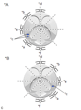
| (b) Position the piston ring set so that the ring ends are as shown in the illustration. NOTICE: Do not align the ring ends. |
|
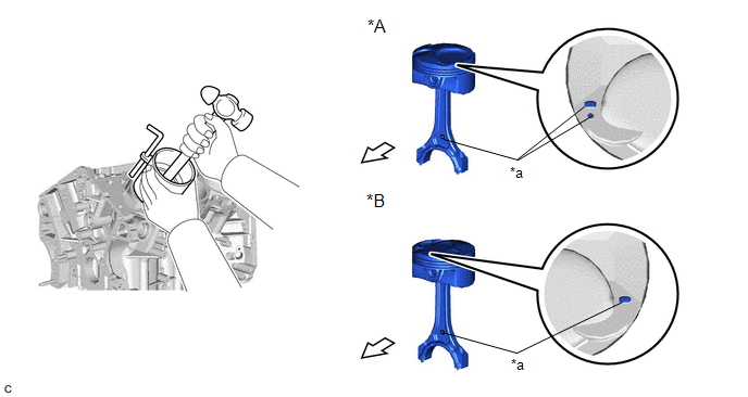
(c) Using a piston ring compressor, push the piston and connecting rod sub-assembly into the cylinder with the front mark of the piston facing the front of the engine.
|
*A | for Bank 1 |
*B | for Bank 2 |
|
*a | Front Mark |
|
Front of Engine |
NOTICE:
Match the connecting rod cap with the connecting rod sub-assembly.
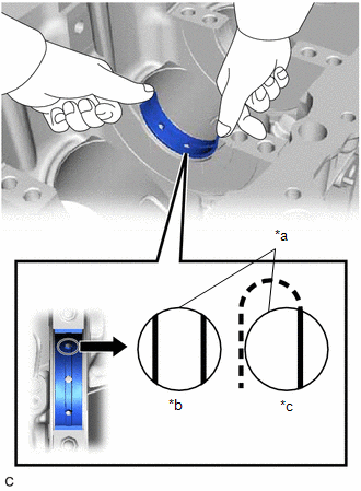
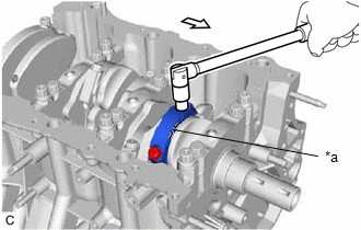
(d) Check that the front mark of the connecting rod cap is facing the front of the engine.
|
*a | Front Mark |
|
|
Front of Engine |
(e) Apply a light coat of engine oil to the threads and under the heads of the connecting rod bolts.
(f) Install the 2 connecting rod bolts.
HINT:
The connecting rod bolts are tightened in 2 progressive steps.
(g) Step 1:
| (1) Alternately tighten the 2 connecting rod bolts in several steps. Torque: 24.5 N·m {250 kgf·cm, 18 ft·lbf} |
|
(h) Step 2:
|
*a | Paint Mark |
|
*b | Turn 90° |
|
|
Front of Engine |
(1) Mark the front of each connecting rod bolt with paint.
(2) Further tighten the connecting rod bolts 90° as shown in the illustration.
(3) Check that the paint marks are now at a 90° angle to the front.
(i) Confirm that the crankshaft turns smoothly.
(j) Check the connecting rod thrust clearance.
Click here
READ NEXT:
 Precaution
PRECAUTION
HINT:
Any digits beyond the 1/100 mm (1/1000 in.) place for standard, minimum and maximum values should be used as a reference only.
When both standard and maximum or minimum val
Components
COMPONENTS ILLUSTRATION
*A w/ Stud Bolt
- -
*1 VALVE SPRING RETAINER LOCK
*2 VALVE SPRING RETAINER
*3 INNER COMPRESSION SPRING
*4 INTAKE VALVE S
SEE MORE:
Cruise Control Input Processor (P160700)
DESCRIPTION When the ECM detects that it is not functioning normally, DTC P160700 is stored.
DTC No. Detection Item
DTC Detection Condition Trouble Area
MIL DTC Output from
P160700 Cruise Control Input Processor
When the ignition switch is ON and control of vehi
Components
COMPONENTS ILLUSTRATION
*1 STEERING WHEEL ASSEMBLY
- -
Tightening torque for "Major areas involving basic vehicle performance such as moving/turning/stopping" : N*m (kgf*cm, ft.*lbf)
- - ILLUSTRATION
*1 LOWER STEERING COLUMN COVER
