Toyota Camry (XV70): Components
COMPONENTS
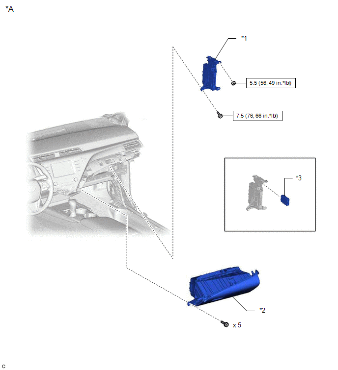
ILLUSTRATION
|
*A | w/ Smart Key System |
- | - |
|
*1 | ECU INTEGRATION BOX RH |
*2 | LOWER INSTRUMENT PANEL SUB-ASSEMBLY |
|
*3 | CENTRAL GATEWAY ECU (NETWORK GATEWAY ECU) |
- | - |
.png) |
N*m (kgf*cm, ft.*lbf): Specified torque |
- | - |
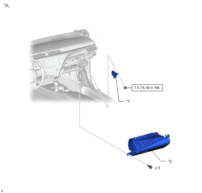
ILLUSTRATION
|
*A | w/o Smart Key System |
- | - |
|
*1 | CENTRAL GATEWAY ECU (NETWORK GATEWAY ECU) |
*2 | LOWER INSTRUMENT PANEL SUB-ASSEMBLY |
|
|
N*m (kgf*cm, ft.*lbf): Specified torque |
- | - |
READ NEXT:
 Removal
REMOVAL CAUTION / NOTICE / HINT
The necessary procedures (adjustment, calibration, initialization, or registration) that must be performed after parts are removed and installed, or replaced during c
Installation
INSTALLATION CAUTION / NOTICE / HINT PROCEDURE
1. INSTALL CENTRAL GATEWAY ECU (NETWORK GATEWAY ECU) (w/o Smart Key System)
(a) Engage the clamp. (b) Connect the central gateway ECU (network gatewa
SEE MORE:
Summary of functions
The multi-information display presents the driver with a variety of driving-
related data, such as the current outside temperature. The multi-information
display can also be used to change the display settings
and other settings.
Indicators
Driving assist system status display area
Disp
FL Speed Sensor Wrong Installation (X0451)
DESCRIPTION
Code Tester Display
Measurement Item Trouble Area
X0451 FL Speed Sensor Wrong Installation
History of front speed sensor LH being installed incorrectly
Front speed sensor LH PROCEDURE
1.
CHECK FOR DTCs (HEALTH CHECK) (a) Perform the H
© 2023-2026 Copyright www.tocamry.com
