Toyota Camry (XV70): Parts Location
Toyota Camry Repair Manual XV70 (2018-2024) / Engine, Hybrid System / 2gr-fks (intake / Exhaust) / Intake System / Parts Location
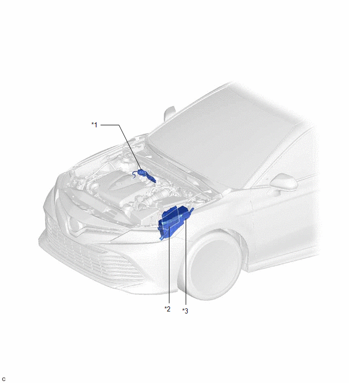
PARTS LOCATION
ILLUSTRATION
|
*1 | INTAKE AIR CONTROL VALVE (for ACIS) |
*2 | ECM |
|
*3 | ENGINE ROOM RELAY BLOCK AND JUNCTION BLOCK ASSEMBLY - EFI NO. 1 FUSE | - |
- |
READ NEXT:
 System Diagram
SYSTEM DIAGRAM
*1 Throttle Body with Motor Assembly
*2 Intake Air Control Valve (for ACIS)
*3 Intake Air Control Valve Actuator (for ACIS)
*4 ECM
*5 Vac
On-vehicle Inspection
ON-VEHICLE INSPECTION CAUTION / NOTICE / HINT
The necessary procedures (adjustment, calibration, initialization or registration) that must be performed after parts are removed and installed, or repl
Parts Location
PARTS LOCATION ILLUSTRATION
*1 INTAKE AIR CONTROL VALVE (for ACIS)
*2 ECM
*3 ENGINE ROOM RELAY BLOCK AND JUNCTION BLOCK ASSEMBLY
- EFI NO. 1 FUSE -
-
SEE MORE:
Headlight Dimmer Switch Circuit
DESCRIPTION The steering sensor receives the following switch information:
Light control switch in DRL OFF*, tail, head or AUTO position
Dimmer switch in high, low or high flash (pass) position
*: w/ DRL OFF Switch
WIRING DIAGRAM
CAUTION / NOTICE / HINT
NOTICE: Be
Installation
INSTALLATION CAUTION / NOTICE / HINT
HINT:
Use the same procedure for the RH side and LH side.
The following procedure is for the LH side.
PROCEDURE 1. PRECAUTION NOTICE:
After turning the ignition switch off, waiting time may be required before disconnecting the cable from the
© 2023-2026 Copyright www.tocamry.com
