Toyota Camry (XV70): System Diagram
Toyota Camry Repair Manual XV70 (2018-2024) / Engine, Hybrid System / 2gr-fks (intake / Exhaust) / Intake System / System Diagram
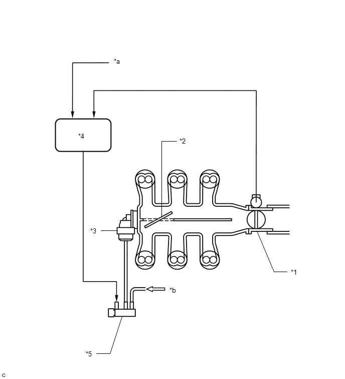
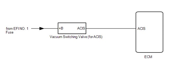
SYSTEM DIAGRAM
|
*1 | Throttle Body with Motor Assembly |
*2 | Intake Air Control Valve (for ACIS) |
|
*3 | Intake Air Control Valve Actuator (for ACIS) |
*4 | ECM |
|
*5 | Vacuum Switching Valve (for ACIS) |
- | - |
|
*a | Engine Speed Signal |
*b | from Vacuum Pump |
READ NEXT:
 On-vehicle Inspection
ON-VEHICLE INSPECTION CAUTION / NOTICE / HINT
The necessary procedures (adjustment, calibration, initialization or registration) that must be performed after parts are removed and installed, or repl
Parts Location
PARTS LOCATION ILLUSTRATION
*1 INTAKE AIR CONTROL VALVE (for ACIS)
*2 ECM
*3 ENGINE ROOM RELAY BLOCK AND JUNCTION BLOCK ASSEMBLY
- EFI NO. 1 FUSE -
-
System Diagram
SYSTEM DIAGRAM
*1 Throttle Body with Motor Assembly
*2 Intake Air Control Valve (for ACIS)
*3 Intake Air Control Valve Actuator (for ACIS)
*4 ECM
*5 Vac
SEE MORE:
Rear Disc Brake Pad(w/o Electric Parking Brake System)
ComponentsCOMPONENTS ILLUSTRATION
*1 REAR DISC BRAKE ANTI-SQUEAL SHIM KIT
*2 REAR DISC BRAKE PAD
*3 REAR DISC BRAKE CYLINDER ASSEMBLY
*4 REAR DISC BRAKE PAD WEAR INDICATOR PLATE
*5 REAR NO. 1 DISC BRAKE ANTI-SQUEAL SHIM
*6 REAR FLEXIBLE HOSE
Alarm
The alarm
The alarm uses light and sound to give an alert when an intrusion is
detected.
The alarm is triggered in the following situations when the alarm is
set:
Vehicles without a smart key system
A locked door is unlocked or opened in any way other than using
the wireless remote cont
© 2023-2026 Copyright www.tocamry.com
