Toyota Camry (XV70): Parts Location
PARTS LOCATION
ILLUSTRATION
|
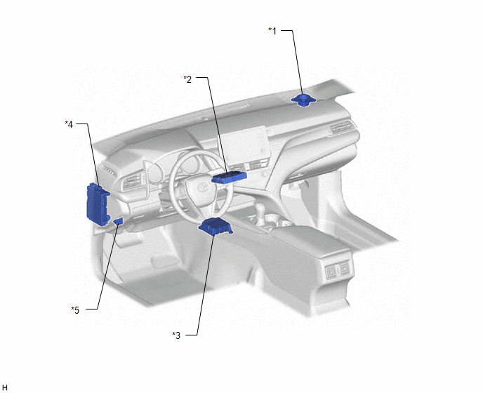
*1 | FRONT NO. 2 SPEAKER ASSEMBLY (RH) |
*2 | DCM (TELEMATICS TRANSCEIVER) - BUB (BACK-UP BATTERY) |
|
*3 | AIRBAG SENSOR ASSEMBLY |
*4 | INSTRUMENT PANEL JUNCTION BLOCK ASSEMBLY - DCM FUSE - ECU-IG2 NO. 3 FUSE |
|
*5 | DLC3 |
- | - |
ILLUSTRATION
|
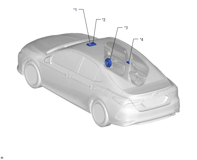
*1 | TELEPHONE MICROPHONE ASSEMBLY |
*2 | ROOF CONSOLE BOX SUB-ASSEMBLY - MANUAL (SOS) SWITCH |
|
*3 | FRONT NO. 1 SPEAKER ASSEMBLY (RH) |
*4 | TELEPHONE AND GPS ANTENNA (for Roof Side) - Telephone Main - GPS |
ILLUSTRATION
|
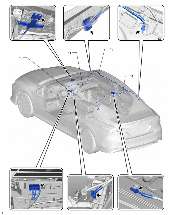
*1 | TELEPHONE AND GPS ANTENNA CORD (ANTENNA CORD SUB-ASSEMBLY (for Type A)) |
*2 | TELEPHONE AND GPS ANTENNA CORD (ANTENNA CORD SUB-ASSEMBLY (for Type B)) |
|
*3 | TELEPHONE AND GPS ANTENNA CORD (NO. 2 ANTENNA CORD SUB-ASSEMBLY) |
*4 | TELEPHONE AND GPS ANTENNA CORD (NO. 5 ANTENNA CORD SUB-ASSEMBLY) |
READ NEXT:
 System Diagram
SYSTEM DIAGRAM
System Description
SYSTEM DESCRIPTION DESCRIPTION (a) Safety Connect performs ACN (Automatic Collision Notification), manual emergency calling, stolen vehicle tracking and roadside assistance service by, audio and data
How To Proceed With Troubleshooting
CAUTION / NOTICE / HINT
HINT:
Use the following procedure to troubleshoot the safety connect system.
*: Use the Techstream.
PROCEDURE
1. VEHICLE BROUGHT TO WORKSHOP
SEE MORE:
Removal
REMOVAL CAUTION / NOTICE / HINT
The necessary procedures (adjustment, calibration, initialization, or registration) that must be performed after parts are removed and installed, or replaced during rear door lock with motor assembly removal/installation are shown below. Necessary Procedure After Par
Sensor (Motor) Failure (B2341,B2344)
DESCRIPTION When the sliding roof ECU (sliding roof drive gear sub-assembly) detects a motor malfunction and the sliding roof operation is stopped, DTC B2341 is stored.
When the sliding roof ECU (sliding roof drive gear sub-assembly) detects a gear position malfunction and the sliding roof operat
© 2023-2026 Copyright www.tocamry.com
