Toyota Camry (XV70): Removal
REMOVAL
CAUTION / NOTICE / HINT
The necessary procedures (adjustment, calibration, initialization or registration) that must be performed after parts are removed and installed, or replaced during VVT sensor removal/installation are shown below.
Necessary Procedures After Parts Removed/Installed/Replaced|
Replaced Part or Performed Procedure |
Necessary Procedure | Effect/Inoperative Function when Necessary Procedure not Performed |
Link |
|---|---|---|---|
| Inspection after repair |
|
|
PROCEDURE
1. REMOVE INTAKE AIR SURGE TANK ASSEMBLY
Click here
.gif)
2. REMOVE VVT SENSOR (for Intake Side of Bank 1)
| (a) Disconnect the VVT sensor connector. |
|
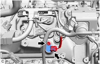
(b) Remove the bolt and VVT sensor from the cylinder head cover sub-assembly.
NOTICE:
If the VVT sensor has been struck or dropped, replace it.
3. REMOVE VVT SENSOR (for Exhaust Side of Bank 1)
| (a) Disconnect the VVT sensor connector. |
|
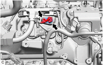
(b) Remove the bolt and VVT sensor from the cylinder head cover sub-assembly.
NOTICE:
If the VVT sensor has been struck or dropped, replace it.
4. REMOVE VVT SENSOR (for Intake Side of Bank 2)
| (a) Disconnect the VVT sensor connector. |
|
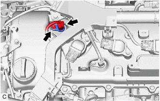
(b) Remove the bolt and VVT sensor from the cylinder head cover sub-assembly LH.
NOTICE:
If the VVT sensor has been struck or dropped, replace it.
5. REMOVE VVT SENSOR (for Exhaust Side of Bank 2)
| (a) Disconnect the VVT sensor connector. |
|
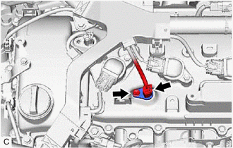
(b) Remove the bolt and VVT sensor from the cylinder head cover sub-assembly LH.
NOTICE:
If the VVT sensor has been struck or dropped, replace it.
READ NEXT:
 Installation
INSTALLATION PROCEDURE 1. INSTALL VVT SENSOR (for Exhaust Side of Bank 2)
(a) Apply a light coat of engine oil to the O-ring of the VVT sensor. NOTICE:
If reusing the VVT sensor, be sure to inspec
Crankshaft Position Sensor
ComponentsCOMPONENTS ILLUSTRATION
*1 CRANKSHAFT POSITION SENSOR
*2 CRANKSHAFT POSITION SENSOR PROTECTOR
N*m (kgf*cm, ft.*lbf): Specified torque
- - Remova
SEE MORE:
Automatic High Beam Switch Indicator does not Come ON
DESCRIPTION When the automatic high beam system is on, the main body ECU (multiplex network body ECU) illuminates the auto high beam switch indicator. WIRING DIAGRAM
CAUTION / NOTICE / HINT
NOTICE:
Inspect the fuses for circuits related to this system before performing the following pro
Dynamic radar cruise
control
Summary of functions
In vehicle-to-vehicle distance control mode, the vehicle automatically
accelerates and decelerates to match the speed changes of the preceding
vehicle even if the accelerator pedal is not depressed. In constant
speed control mode, the vehicle runs at a fixed speed.
Use the
