Toyota Camry (XV70): Installation
INSTALLATION
PROCEDURE
1. INSTALL HOLE PLUG
| (a) Install the 10 hole plugs to the rear suspension member sub-assembly. HINT: There are 2 different shapes of hole plug. |
|
.png)
2. INSTALL REAR SUSPENSION MEMBER FRONT BODY MOUNTING CUSHION (for LH Side)
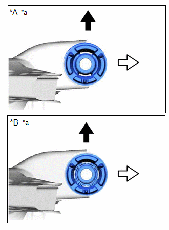
(a) Confirm the installation direction and temporarily install a new rear suspension member front body mounting cushion.
NOTICE:
- Position the rear suspension member front body mounting cushion in the correct direction.
- Do not apply lubricant to the outer sleeve of the rear suspension member front body mounting cushion.
|
*A | Type A |
|
*B | Type B |
|
*a | View from Underneath |
.png) |
Front of the Vehicle |
.png) |
Outside of the Vehicle |
| (b) Install SST as shown in the illustration. SST: 09570-24011 SST: 09830-10010 09830-01010 09830-01020 09830-01040 09830-01050 NOTICE: Apply molybdenum grease to the threads and tip of the SST center bolt before use. |
|

(c) Using SST, install the rear suspension member front body mounting cushion until there is no clearance between the rear suspension member sub-assembly and rear suspension member front body mounting cushion.
SST: 09570-24011
SST: 09830-10010
09830-01010
09830-01020
09830-01040
09830-01050
NOTICE:
If the rear suspension member sub-assembly is scratched, apply paint to the scratched areas of the rear suspension member sub-assembly.

|
*a | Hold |
.png) |
Turn |
(d) Remove SST from the rear suspension member sub-assembly.
3. INSTALL REAR SUSPENSION MEMBER FRONT BODY MOUNTING CUSHION (for RH Side)
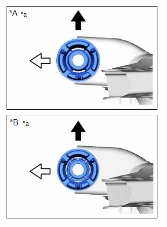
(a) Confirm the installation direction and temporarily install a new rear suspension member front body mounting cushion.
NOTICE:
- Position the rear suspension member front body mounting cushion in the correct direction.
- Do not apply lubricant to the outer sleeve of the rear suspension member front body mounting cushion.
|
*A | Type A |
|
*B | Type B |
|
*a | View from Underneath |
|
|
Front of the Vehicle |
|
|
Outside of the Vehicle |
(b) Install SST using the same procedure as for the rear suspension member front body mounting cushion (for LH Side).
SST: 09570-24011
SST: 09830-10010
09830-01010
09830-01020
09830-01040
09830-01050
NOTICE:
Apply molybdenum grease to the threads and tip of the SST center bolt before use.
(c) Using SST, install the rear suspension member front body mounting cushion until there is no clearance between the rear suspension member sub-assembly and rear suspension member front body mounting cushion.
SST: 09570-24011
SST: 09830-10010
09830-01010
09830-01020
09830-01040
09830-01050
NOTICE:
If the rear suspension member sub-assembly is scratched, apply paint to the scratched areas of the rear suspension member sub-assembly.
HINT:
Perform the same procedure as for the rear suspension member front body mounting cushion (for LH Side).
(d) Remove SST from the rear suspension member sub-assembly.
4. INSTALL REAR SUSPENSION MEMBER REAR BODY MOUNT CUSHION LH
(a) Confirm the installation direction and temporarily install a new rear suspension member rear body mount cushion LH.
NOTICE:
- Position the rear suspension member rear body mount cushion LH in the correct direction.
- Do not apply lubricant to the outer sleeve of the rear suspension member rear body mount cushion LH.
.png)
|
*A | Type A |
|
*B | Type B |
|
*a | View from Underneath |
|
|
Front of the Vehicle |
|
|
Outside of the Vehicle |
| (b) Install SST as shown in the illustration. SST: 09710-28031 09711-02030 09711-02040 94622-51200 SST: 09950-60021 09951-00720 09951-00890 NOTICE: Apply molybdenum grease to the threads and tip of the SST center bolt before use. |
|

(c) Using SST, install the rear suspension member rear body mount cushion LH until there is no clearance between the rear suspension member sub-assembly and rear suspension member rear body mount cushion LH.
SST: 09710-28031
09711-02030
09711-02040
94622-51200
SST: 09950-60021
09951-00720
09951-00890
NOTICE:
If the rear suspension member sub-assembly is scratched, apply paint to the scratched areas of the rear suspension member sub-assembly.

|
*a | Hold |
|
|
Turn |
(d) Remove SST from the rear suspension member sub-assembly.
5. INSTALL REAR SUSPENSION MEMBER REAR BODY MOUNT CUSHION RH
(a) Confirm the installation direction and temporarily install a new rear suspension member rear body mount cushion RH.
NOTICE:
- Position the rear suspension member rear body mount cushion RH in the correct direction.
- Do not apply lubricant to the outer sleeve of the rear suspension member rear body mount cushion RH.
.png)
|
*A | Type A |
|
*B | Type B |
|
*a | View from Underneath |
|
|
Front of the Vehicle |
|
|
Outside of the Vehicle |
(b) Install SST using the same procedure as for the rear suspension member rear body mount cushion LH.
SST: 09710-28031
09711-02030
09711-02040
94622-51200
SST: 09950-60021
09951-00720
09951-00890
NOTICE:
Apply molybdenum grease to the threads and tip of the SST center bolt before use.
(c) Using SST, install the rear suspension member rear body mount cushion RH until there is no clearance between the rear suspension member sub-assembly and rear suspension member rear body mount cushion RH.
SST: 09710-28031
09711-02030
09711-02040
94622-51200
SST: 09950-60021
09951-00720
09951-00890
NOTICE:
If the rear suspension member sub-assembly is scratched, apply paint to the scratched areas of the rear suspension member sub-assembly.
HINT:
Perform the same procedure as for the rear suspension member rear body mount cushion LH.
(d) Remove SST from the rear suspension member sub-assembly.
6. INSTALL REAR UPPER CONTROL ARM ASSEMBLY LH
Click here .gif)
7. INSTALL REAR UPPER CONTROL ARM ASSEMBLY RH
HINT:
Perform the same procedure as for the LH side.
8. INSTALL WIRE HARNESS
(a) Engage the 2 clamps and install the wire harness to the rear suspension member sub-assembly.
9. INSTALL REAR SUSPENSION MEMBER SUB-ASSEMBLY
(a) Install the 4 rear suspension member cushions to the rear suspension member sub-assembly.
HINT:
When reusing the rear suspension member cushion, make sure to check its identification mark and install it to the correct position.
(b) Using an engine lifter and 4 attachments or equivalent tools, support the rear suspension member sub-assembly as shown in the illustration.
.png)
- The rear suspension member sub-assembly is a very heavy component. Make sure that it is supported securely.
- If the rear suspension member sub-assembly is not securely supported, it may drop, resulting in serious injury.
NOTICE:
- Use attachments or equivalent tools to keep the rear suspension member sub-assembly level.
- Keep supporting the rear suspension member sub-assembly until the installation has been completed.
.png)
|
*a | Engine Lifter |
|
*b | Attachment |
.png) |
Attachment Placement Location |
(c) Raise the rear suspension member sub-assembly until there is no clearance between the rear suspension member sub-assembly and vehicle.
| (d) Install the rear suspension member sub-assembly with the 2 rear suspension member lower stoppers, rear suspension member lower brace LH and rear suspension member lower brace RH, 2 bolts and 6 nuts. Torque: Bolt A : 158 N |
READ NEXT:
 Problem Symptoms Table
PROBLEM SYMPTOMS TABLE HINT: Use the table below to help determine the cause of problem symptoms. If multiple suspected areas are listed, the potential causes of the symptoms are listed in order of pr
SEE MORE:
Installation
INSTALLATION PROCEDURE 1. INSTALL REAR STABILIZER BUSHING
(a) Install the 2 rear stabilizer bushings to the rear stabilizer bar.
NOTICE: Be sure to install the rear stabilizer bushings so that each cutout faces the front of the vehicle.
2. INSTALL REAR NO. 1 STABILIZER BAR BRACKET (a) Install
Black Screen
PROCEDURE
1. CHECK DISPLAY SETTING
(a) Check that the display is not in screen off mode. OK: The display setting is not in screen off mode.
NG
CHANGE SCREEN TO SCREEN ON MODE
OK
2.
CHECK IMAGE QUALITY SETTING (a) Check that the
