
Toyota Camry (XV70): Installation
INSTALLATION
PROCEDURE
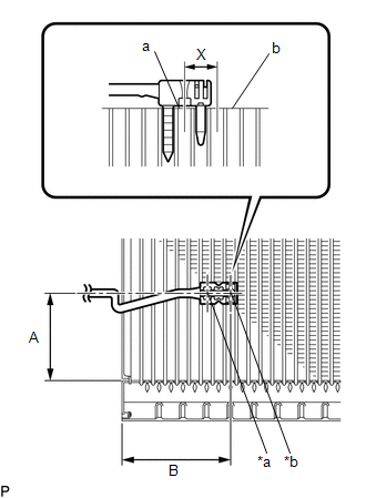
1. INSTALL NO. 1 COOLER THERMISTOR
| (a) Install the No. 1 cooler thermistor as shown in the illustration. Installation Position:
NOTICE:
|
|
2. INSTALL NO. 1 COOLER EVAPORATOR SUB-ASSEMBLY
Click here
.gif)
3. INSTALL COOLER EXPANSION VALVE
Click here
4. INSTALL GROMMET SUB-ASSEMBLY
Click here
5. INSTALL HEATER RADIATOR UNIT SUB-ASSEMBLY
Click here
6. INSTALL HEATER CLAMP
Click here
7. INSTALL HEATER PIPE GROMMET
Click here
8. INSTALL NO. 1 AIR CONDITIONING RADIATOR DAMPER SERVO SUB-ASSEMBLY
Click here
9. INSTALL AIR CONDITIONING HARNESS ASSEMBLY
Click here
10. INSTALL BLOWER ASSEMBLY
Click here
READ NEXT:
SEE MORE:
 Portable Player cannot be Registered
CAUTION / NOTICE / HINT HINT: Some versions of "Bluetooth" compatible audio players may not function properly, or the functions may be limited using the radio and display receiver assembly, even if the portable audio player itself can play files.
Click here
PROCEDURE
1.
CHECK
Problem Symptoms Table
PROBLEM SYMPTOMS TABLE
HINT:
Use the table below to help determine the cause of problem symptoms. If multiple suspected areas are listed, the potential causes of the symptoms are listed in order of probability in the "Suspected Area" column of the table. Check each symptom by checking the susp
© 2023-2026 Copyright www.tocamry.com
