
Toyota Camry (XV70): Key Reminder Buzzer does not Sound
DESCRIPTION
The key reminder warning buzzer sounds when the driver door is opened while the ignition switch is off or ACC. The key reminder warning buzzer is activated when the main body ECU (multiplex network body ECU) sends an unlock warning switch signal and driver door courtesy light switch signal to the combination meter assembly via CAN communication.
WIRING DIAGRAM
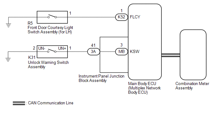
CAUTION / NOTICE / HINT
NOTICE:
- The key reminder warning system uses the CAN communication system. Inspect the communication function by following How to Proceed with Troubleshooting. Troubleshoot the key reminder warning system after confirming that the communication systems are functioning properly.
Click here
.gif)
PROCEDURE
|
1. | PERFORM ACTIVE TEST USING TECHSTREAM (Buzzer Operation) |
(a) Connect the Techstream to the DLC3.
(b) Turn the ignition switch to ON.
(c) Turn the Techstream on.
(d) Enter the following menus: Body Electrical / Combination Meter / Active Test.
(e) Perform the Active Test according to the display on the Techstream.
Body Electrical > Combination Meter > Active Test|
Tester Display | Measurement Item |
Control Range | Diagnostic Note |
|---|---|---|---|
|
Buzzer Operation (800Hz, Vol L, W/ Damping) |
Combination meter buzzer
| ON |
- |
|
Tester Display |
|---|
| Buzzer Operation (800Hz, Vol L, W/ Damping) |
|
Result | Proceed to |
|---|---|
|
Combination meter buzzer sounds |
A |
| Combination meter buzzer does not sound |
B |
| B |
.gif) | REPLACE COMBINATION METER ASSEMBLY
|
|
.gif)
| 2. |
READ VALUE USING TECHSTREAM (FL Door Courtesy SW) |
(a) Enter the following menus: Body Electrical / Main Body / Data List.
(b) Read the Data List according to the display on the Techstream.
Body Electrical > Main Body > Data List|
Tester Display | Measurement Item |
Range | Normal Condition |
Diagnostic Note |
|---|---|---|---|---|
|
FL Door Courtesy SW | Front door courtesy light switch assembly (for LH) signal |
OFF or ON | OFF: Front door LH closed ON: Front door LH open |
- |
|
Tester Display |
|---|
| FL Door Courtesy SW |
OK:
The Techstream indicates ON or OFF according to the driver door conditions shown in the table.
| NG | | GO TO STEP 7 |
|
| 3. |
READ VALUE USING TECHSTREAM (Key Unlock Warning SW) |
(a) Read the Data List according to the display on the Techstream.
Body Electrical > Main Body > Data List|
Tester Display | Measurement Item |
Range | Normal Condition |
Diagnostic Note |
|---|---|---|---|---|
|
Key Unlock Warning SW | Unlock warning switch signal |
OFF or ON | OFF: No key in ignition key cylinder ON: Key in ignition key cylinder |
- |
|
Tester Display |
|---|
| Key Unlock Warning SW |
OK:
The Techstream indicates ON or OFF according to whether the key is in the ignition key cylinder.
| OK | | REPLACE MAIN BODY ECU (MULTIPLEX NETWORK BODY ECU)
|
|
| 4. |
INSPECT UNLOCK WARNING SWITCH ASSEMBLY |
(a) Remove the unlock warning switch assembly.
Click here
(b) Inspect the unlock warning switch assembly.
Click here
| NG | | REPLACE UNLOCK WARNING SWITCH ASSEMBLY |
|
| 5. |
CHECK HARNESS AND CONNECTOR (UNLOCK WARNING SWITCH ASSEMBLY - INSTRUMENT PANEL JUNCTION BLOCK ASSEMBLY) |
(a) Disconnect the 3A instrument panel junction block assembly connector.
(b) Measure the resistance according to the value(s) in the table below.
Standard Resistance:
|
Tester Connection | Condition |
Specified Condition |
|---|---|---|
|
3A-41 - K31-1 (UN+) | Always |
Below 1 ? |
|
K31-2 (UN-) - Body ground |
Always | Below 1 ? |
|
K31-1 (UN+) or 3A-41 - Body ground |
Always | 10 k? or higher |
| NG | | REPAIR OR REPLACE HARNESS OR CONNECTOR |
|
| 6. |
INSPECT INSTRUMENT PANEL JUNCTION BLOCK ASSEMBLY |
(a) Remove the instrument panel junction block assembly.
Click here
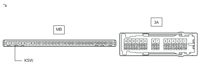
|
*a | Component without harness connected (Instrument Panel Junction Block Assembly) |
- | - |
(b) Remove the main body ECU (multiplex network body ECU) from the instrument panel junction block assembly.
(c) Measure the resistance according to the value(s) in the table below.
Standard Resistance:
|
Tester Connection | Condition |
Specified Condition |
|---|---|---|
|
3A-41 - MB-3 (KSW) | Always |
Below 1 ? |
| OK | | REPLACE MAIN BODY ECU (MULTIPLEX NETWORK BODY ECU)
|
| NG | | REPLACE INSTRUMENT PANEL JUNCTION BLOCK ASSEMBLY
|
| 7. |
INSPECT FRONT DOOR COURTESY LIGHT SWITCH ASSEMBLY (for LH) |
(a) Remove the front door courtesy light switch assembly (for LH).
Click here
(b) Inspect the front door courtesy light switch assembly (for LH).
Click here
| NG | | REPLACE FRONT DOOR COURTESY LIGHT SWITCH ASSEMBLY (for LH) |
|
| 8. |
CHECK HARNESS AND CONNECTOR (FRONT DOOR COURTESY LIGHT SWITCH ASSEMBLY (for LH) - MAIN BODY ECU (MULTIPLEX NETWORK BODY ECU)) |
(a) Disconnect the K52 main body ECU (multiplex network body ECU) connector.
(b) Measure the resistance according to the value(s) in the table below.
Standard Resistance:
|
Tester Connection | Condition |
Specified Condition |
|---|---|---|
|
R5-1 - K52-1 (FLCY) | Always |
Below 1 ? |
|
R5-1 or K52-1 (FLCY) - Body ground |
Always | 10 k? or higher |
| OK | | REPLACE MAIN BODY ECU (MULTIPLEX NETWORK BODY ECU)
|
| NG | | REPAIR OR REPLACE HARNESS OR CONNECTOR |
READ NEXT:
 Luggage Compartment Door Lock
ComponentsCOMPONENTS ILLUSTRATION
*1 LUGGAGE COMPARTMENT DOOR COVER
*2 LUGGAGE COMPARTMENT DOOR INSIDE HANDLE
*3 LUGGAGE COMPARTMENT DOOR LOCK ASSEMBLY
*4 LUGGAGE DOOR
Precaution
PRECAUTION PRECAUTION FOR DISCONNECTING CABLE FROM NEGATIVE BATTERY TERMINAL
NOTICE: When disconnecting the cable from the negative (-) battery terminal, initialize the following systems after the ca
SEE MORE:
Diagnostic Trouble Code Chart
DIAGNOSTIC TROUBLE CODE CHART Sliding Roof System
DTC No. Detection Item
Link B2341
Sensor (Motor) Failure
B2342 Switch Failure
B2343 Position Initialization Incomplete
B2344 Position Failure
Installation
INSTALLATION CAUTION / NOTICE / HINT
HINT:
Use the same procedure for the RH side and LH side.
The following procedure is for the LH side.
PROCEDURE 1. INSTALL FRONT DRIVE SHAFT HOLE SNAP RING
(a) Install a new front drive shaft hole snap ring. NOTICE: Face the end gap of the front d
