
Toyota Camry (XV70): Lost Communication with EMV Missing Message (B132187)
DESCRIPTION
The combination meter assembly and radio and display receiver assembly communicate via local bus communication. This allows audio and visual system information to be displayed on the multi-information display.
This DTC is stored when a communication error occurs between the radio and display receiver assembly and combination meter assembly.
|
DTC No. | Detection Item |
DTC Detection Condition | Trouble Area |
Memory | Note |
|---|---|---|---|---|---|
|
B132187 | Lost Communication with EMV Missing Message |
Diagnosis Condition:
Malfunction Status:
Malfunction Time:
|
| DTC stored |
for 9 Inch Display Type Radio and Display Receiver Assembly |
- *: w/ Headup Display System
WIRING DIAGRAM
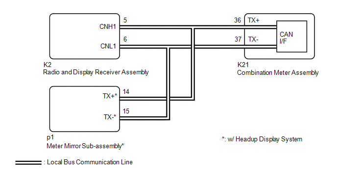
CAUTION / NOTICE / HINT
NOTICE:
When replacing the combination meter assembly, always replace it with a new one. If a combination meter assembly which was installed to another vehicle is used, the information stored in it will not match the information from the vehicle and a DTC may be stored.
PROCEDURE
| 1. |
CONFIRM MODEL |
(a) Choose the model to be inspected.
|
Result | Proceed to |
|---|---|
|
w/o Navigation System |
A |
| w/ Navigation System |
B |
| B |
 | GO TO STEP 3 |
|

| 2. |
CHECK FOR DTC (AUDIO AND VISUAL SYSTEM) |
(a) Check if audio and visual system DTCs are output.
Body Electrical > Navigation System > Trouble Codes|
Result | Proceed to |
|---|---|
|
DTCs are not output | A |
|
DTCs are output | B |
| A |
| GO TO STEP 6 |
| B |
| GO TO AUDIO AND VISUAL SYSTEM |
| 3. |
CHECK FOR DTC (NAVIGATION SYSTEM) |
(a) Check if navigation system DTCs are output.
Body Electrical > Navigation System > Trouble Codes|
Result | Proceed to |
|---|---|
|
DTCs are not output | A |
|
DTCs are output | B |
| B |
| GO TO NAVIGATION SYSTEM |
|
| 4. |
CONFIRM MODEL |
(a) Choose the model to be inspected.
|
Result | Proceed to |
|---|---|
|
w/o Headup Display System |
A |
| w/ Headup Display System |
B |
| B |
| GO TO STEP 7 |
|
| 5. |
REPLACE COMBINATION METER ASSEMBLY |
(a) Replace the combination meter assembly with a new one.
Click here 
|
| 6. |
CHECK COMBINATION METER ASSEMBLY |
(a) Turn the ignition switch to ON and wait 3 seconds.
NOTICE:
A minimum of 3 seconds is required to send/receive the registration information between the combination meter assembly and radio and display receiver assembly.
(b) Operate the steering pad switch assembly and check that the audio tab illuminates.
(c) Check if meter / gauge system DTCs are output.
Body Electrical > Combination Meter > Trouble Codes|
Result | Proceed to |
|---|---|
|
The audio tab illuminates and DTC B132187 is not output |
A |
| The audio tab does not illuminate and DTC B132187 is output |
B |
| A |
| END (COMBINATION METER ASSEMBLY WAS DEFECTIVE) |
| B |
| REPLACE RADIO AND DISPLAY RECEIVER ASSEMBLY |
| 7. |
CHECK FOR DTC (HEADUP DISPLAY SYSTEM) |
(a) Check if headup display system DTCs are output.
Body Electrical > Head Up Display > Trouble Codes|
Result | Proceed to |
|---|---|
|
DTC B132187 is not output |
A |
| DTC B132187 is output |
B |
| A |
| REPLACE COMBINATION METER ASSEMBLY |
| B |
| REPLACE RADIO AND DISPLAY RECEIVER ASSEMBLY |
READ NEXT:
SEE MORE:
 Terminals Of Ecu
TERMINALS OF ECU CHECK INSTRUMENT PANEL JUNCTION BLOCK ASSEMBLY AND MAIN BODY ECU (MULTIPLEX NETWORK BODY ECU)
(a) Disconnect the MB main body ECU (multiplex network body ECU) connector.
Click here (b) Measure the voltage and resistance according to the value(s) in the table below.
HINT: Me
Problem Symptoms Table
PROBLEM SYMPTOMS TABLE
NOTICE:
Depending on the parts that are replaced during vehicle inspection or maintenance, performing initialization, registration or calibration may be needed. Refer to Precaution for Navigation System.
Click here
When replacing the radio and display receiver asse
