Toyota Camry (XV70): Terminals Of Ecu
TERMINALS OF ECU
CHECK INSTRUMENT PANEL JUNCTION BLOCK ASSEMBLY AND MAIN BODY ECU (MULTIPLEX NETWORK BODY ECU)
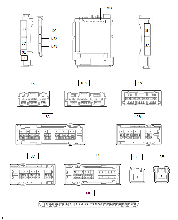
(a) Disconnect the MB main body ECU (multiplex network body ECU) connector.
Click here .gif)
(b) Measure the voltage and resistance according to the value(s) in the table below.
HINT:
Measure the values on the wire harness side with the connectors disconnected.
|
Terminal No. (Symbol) | Wiring Color |
Terminal Description | Condition |
Specified Condition |
|---|---|---|---|---|
|
MB-11 (GND1) - Body ground |
- | Ground |
Always | Below 1 Ω |
|
MB-31 (BECU) - Body ground |
- | Battery power supply |
Always | 11 to 14 V |
|
MB-30 (ACC) - Body ground |
- | ACC power supply |
Ignition switch ACC | 11 to 14 V |
|
Ignition switch off | Below 1 V | |||
|
MB-32 (IG) - Body ground |
- | IG power supply |
Ignition switch ON | 11 to 14 V |
|
Ignition switch off | Below 1 V |
(c) Reconnect the MB main body ECU (multiplex network body ECU) connector.
(d) Check for pulses according to the value(s) in the table below.
|
Terminal No. (Symbol) | Wiring Color |
Terminal Description | Condition |
Specified Condition |
|---|---|---|---|---|
|
3D-25 - Body ground | LA-BE - Body ground |
LIN communication line |
Ignition switch ON | Pulse generation |
|
3B-17 - Body ground* |
L - Body ground | LIN communication line |
Ignition switch ON | Pulse generation |
- *: w/ Sliding Roof System or Panoramic Moon Roof System
CHECK POWER WINDOW REGULATOR MOTOR ASSEMBLY (for Driver Door)

(a) Disconnect the O6 power window regulator motor assembly (for driver door) connector.
(b) Measure the voltage and resistance according to the value(s) in the table below.
HINT:
Measure the values on the wire harness side with the connector disconnected.
|
Terminal No. (Symbol) | Wiring Color |
Terminal Description | Condition |
Specified Condition |
|---|---|---|---|---|
|
O6-2 (B) - Body ground |
GR - Body ground | Battery power supply |
Always | 11 to 14 V |
|
O6-1 (GND) - Body ground |
W-B - Body ground | Ground |
Always | Below 1 Ω |
(c) Reconnect the O6 power window regulator motor assembly (for driver door) connector.
(d) Check for pulses according to the value(s) in the table below.
|
Terminal No. (Symbol) | Wiring Color |
Terminal Description | Condition |
Specified Condition |
|---|---|---|---|---|
|
O6-9 (LIN) - Body ground |
G - Body ground | LIN communication line |
Ignition switch ON | Pulse generation |
CHECK POWER WINDOW REGULATOR MOTOR ASSEMBLY (for Front Passenger Door)

(a) Disconnect the N7 power window regulator motor assembly (for front passenger door) connector.
(b) Measure the voltage and resistance according to the value(s) in the table below.
HINT:
Measure the values on the wire harness side with the connector disconnected.
|
Terminal No. (Symbol) | Wiring Color |
Terminal Description | Condition |
Specified Condition |
|---|---|---|---|---|
|
N7-2 (B) - Body ground |
GR - Body ground | Battery power supply |
Always | 11 to 14 V |
|
N7-1 (GND) - Body ground |
W-B - Body ground | Ground |
Always | Below 1 Ω |
(c) Reconnect the N7 power window regulator motor assembly (for front passenger door) connector.
(d) Check for pulses according to the value(s) in the table below.
|
Terminal No. (Symbol) | Wiring Color |
Terminal Description | Condition |
Specified Condition |
|---|---|---|---|---|
|
N7-9 (LIN) - Body ground |
P - Body ground | LIN communication line |
Ignition switch ON | Pulse generation |
CHECK POWER WINDOW REGULATOR MOTOR ASSEMBLY (for Rear Door RH)

(a) Disconnect the P6 power window regulator motor assembly (for rear door RH) connector.
(b) Measure the voltage and resistance according to the value(s) in the table below.
HINT:
Measure the values on the wire harness side with the connector disconnected.
|
Terminal No. (Symbol) | Wiring Color |
Terminal Description | Condition |
Specified Condition |
|---|---|---|---|---|
|
P6-2 (B) - Body ground |
B - Body ground | Battery power supply |
Always | 11 to 14 V |
|
P6-1 (GND) - Body ground |
W-B - Body ground | Ground |
Always | Below 1 Ω |
(c) Reconnect the P6 power window regulator motor assembly (for rear door RH) connector.
(d) Check for pulses according to the value(s) in the table below.
|
Terminal No. (Symbol) | Wiring Color |
Terminal Description | Condition |
Specified Condition |
|---|---|---|---|---|
|
P6-9 (LIN) - Body ground |
P - Body ground | LIN communication line |
Ignition switch ON | Pulse generation |
CHECK POWER WINDOW REGULATOR MOTOR ASSEMBLY (for Rear Door LH)

(a) Disconnect the Q6 power window regulator motor assembly (for rear door LH) connector.
(b) Measure the voltage and resistance according to the value(s) in the table below.
HINT:
Measure the values on the wire harness side with the connector disconnected.
|
Terminal No. (Symbol) | Wiring Color |
Terminal Description | Condition |
Specified Condition |
|---|---|---|---|---|
|
Q6-2 (B) - Body ground |
B - Body ground | Battery power supply |
Always | 11 to 14 V |
|
Q6-1 (GND) - Body ground |
W-B - Body ground | Ground |
Always | Below 1 Ω |
(c) Reconnect the Q6 power window regulator motor assembly (for rear door LH) connector.
(d) Check for pulses according to the value(s) in the table below.
|
Terminal No. (Symbol) | Wiring Color |
Terminal Description | Condition |
Specified Condition |
|---|---|---|---|---|
|
Q6-9 (LIN) - Body ground |
P - Body ground | LIN communication line |
Ignition switch ON | Pulse generation |
CHECK MULTIPLEX NETWORK MASTER SWITCH ASSEMBLY

(a) Disconnect the O2 multiplex network master switch assembly connector.
(b) Measure the voltage and resistance according to the value(s) in the table below.
HINT:
Measure the values on the wire harness side with the connector disconnected.
|
Terminal No. (Symbol) | Wiring Color |
Terminal Description | Condition |
Specified Condition |
|---|---|---|---|---|
|
O2-11 (B) - Body ground |
LA-R - Body ground | Battery power supply |
Always | 11 to 14 V |
|
O2-12 (GND) - Body ground |
W-B - Body ground | Ground |
Always | Below 1 Ω |
(c) Reconnect the O2 multiplex network master switch assembly connector.
(d) Check for pulses according to the value(s) in the table below.
|
Terminal No. (Symbol) | Wiring Color |
Terminal Description | Condition |
Specified Condition |
|---|---|---|---|---|
|
O2-17 (LIN1) - Body ground |
P - Body ground | LIN communication line |
Ignition switch ON | Pulse generation |
CHECK SLIDING ROOF ECU (SLIDING ROOF DRIVE GEAR SUB-ASSEMBLY) (w/ Sliding Roof System)

(a) Disconnect the V2 sliding roof ECU (sliding roof drive gear sub-assembly) connector.
(b) Measure the voltage and resistance according to the value(s) in the table below.
HINT:
Measure the values on the wire harness side with the connector disconnected.
|
Terminal No. (Symbol) | Wiring Color |
Terminal Description | Condition |
Specified Condition |
|---|---|---|---|---|
|
V2-1 (B) - Body ground |
B - Body ground | Battery power supply |
Always | 11 to 14 V |
|
V2-2 (E) - Body ground |
W-B - Body ground | Ground |
Always | Below 1 Ω |
(c) Reconnect the V2 sliding roof ECU (sliding roof drive gear sub-assembly) connector.
(d) Check for pulses according to the value(s) in the table below.
|
Terminal No. (Symbol) | Wiring Color |
Terminal Description | Condition |
Specified Condition |
|---|---|---|---|---|
|
V2-7 (MPX1) - Body ground |
LA-P - Body ground | LIN communication line |
Ignition switch ON | Pulse generation |
CHECK SLIDING ROOF ECU (SLIDING ROOF DRIVE GEAR ASSEMBLY) (w/ Panoramic Moon Roof System)

(a) Disconnect the q1 sliding roof ECU (sliding roof drive gear assembly) connector.
(b) Measure the voltage and resistance according to the value(s) in the table below.
HINT:
Measure the values on the wire harness side with the connector disconnected.
|
Terminal No. (Symbol) | Wiring Color |
Terminal Description | Condition |
Specified Condition |
|---|---|---|---|---|
|
q1-1 (+B) - Body ground |
L - Body ground | Battery power supply |
Always | 11 to 14 V |
|
q1-2 (E) - Body ground |
W-B - Body ground | Ground |
Always | Below 1 Ω |
(c) Reconnect the q1 sliding roof ECU (sliding roof drive gear assembly) connector.
(d) Check for pulses according to the value(s) in the table below.
|
Terminal No. (Symbol) | Wiring Color |
Terminal Description | Condition |
Specified Condition |
|---|---|---|---|---|
|
q1-7 (LIN) - Body ground |
B - Body ground | LIN communication line |
Ignition switch ON | Pulse generation |
CHECK ROOF SUNSHADE ECU (SLIDING ROOF DRIVE GEAR ASSEMBLY) (w/ Panoramic Moon Roof System)

(a) Disconnect the q2 roof sunshade ECU (sliding roof drive gear assembly) connector.
(b) Measure the voltage and resistance according to the value(s) in the table below.
HINT:
Measure the values on the wire harness side with the connector disconnected.
|
Terminal No. (Symbol) | Wiring Color |
Terminal Description | Condition |
Specified Condition |
|---|---|---|---|---|
|
q2-1 (+B) - Body ground |
G - Body ground | Battery power supply |
Always | 11 to 14 V |
|
q2-2 (E) - Body ground |
W-B - Body ground | Ground |
Always | Below 1 Ω |
(c) Reconnect the q2 roof sunshade ECU (sliding roof drive gear assembly) connector.
(d) Check for pulses according to the value(s) in the table below.
|
Terminal No. (Symbol) | Wiring Color |
Terminal Description | Condition |
Specified Condition |
|---|---|---|---|---|
|
q2-7 (LIN) - Body ground |
B - Body ground | LIN communication line |
Ignition switch ON | Pulse generation |
CHECK CERTIFICATION ECU (SMART KEY ECU ASSEMBLY) (w/ Smart Key System)
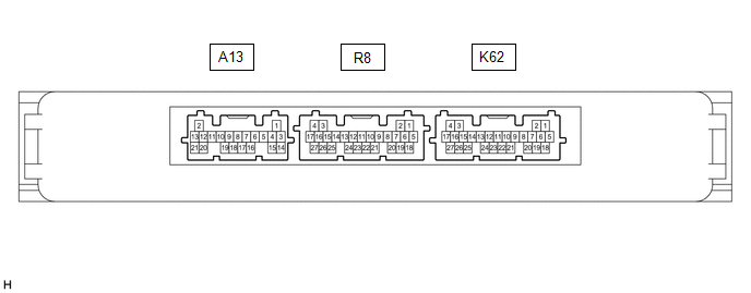
(a) Disconnect the K62 certification ECU (smart key ECU assembly) connector.
(b) Measure the voltage and resistance according to the value(s) in the table below.
HINT:
Measure the values on the wire harness side with the connector disconnected.
|
Terminal No. (Symbol) | Wiring Color |
Terminal Description | Condition |
Specified Condition |
|---|---|---|---|---|
|
K62-18 (E) - Body ground |
W-B - Body ground | Ground |
Always | Below 1 Ω |
|
K62-4 (+B) - Body ground |
W - Body ground | Battery power supply |
Always | 11 to 14 V |
(c) Reconnect the K62 certification ECU (smart key ECU assembly) connector.
(d) Check for pulses according to the value(s) in the table below.
|
Terminal No. (Symbol) | Wiring Color |
Terminal Description | Condition |
Specified Condition |
|---|---|---|---|---|
|
K62-13 (LIN) - Body ground |
GR - Body ground | LIN communication line |
Ignition switch ON | Pulse generation |
CHECK ID CODE BOX (IMMOBILISER CODE ECU) (w/ Smart Key System)

(a) Disconnect the K152 ID code box (immobiliser code ECU) connector.
(b) Measure the voltage and resistance according to the value(s) in the table below.
HINT:
Measure the values on the wire harness side with the connector disconnected.
|
Terminal No. (Symbol) | Wiring Color |
Terminal Description | Condition |
Specified Condition |
|---|---|---|---|---|
|
K152-5 (GND) - Body ground |
W-B - Body ground | Ground |
Always | Below 1 Ω |
|
K152-1 (+B) - Body ground |
LA-GR - Body ground | +B power supply |
Power switch off | 11 to 14 V |
(c) Reconnect the K152 ID code box (immobiliser code ECU) connector.
(d) Check for pulses according to the value(s) in the table below.
|
Terminal No. (Symbol) | Wiring Color |
Terminal Description | Condition |
Specified Condition |
|---|---|---|---|---|
|
K152-2 (LIN1) - Body ground |
GR - Body ground | LIN communication line |
Power switch on (IG) |
Pulse generation |
READ NEXT:
 Diagnosis System
DIAGNOSIS SYSTEM DESCRIPTION The main body ECU (multiplex network body ECU) and certification ECU (smart key ECU assembly) control the LIN communication system. LIN communication system data and Diagn
Dtc Check / Clear
DTC CHECK / CLEAR CHECK DTC (a) Connect the Techstream to the DLC3.
(b) Turn the ignition switch to ON. (c) Turn the Techstream on.
(d) Enter the following menus: Body Electrical / Main Body or Sm
Data List / Active Test
DATA LIST / ACTIVE TEST DATA LIST HINT:
Using the Techstream to read the Data List allows the values or states of switches, sensors, actuators and other items to be read without removing any parts.
SEE MORE:
Components
COMPONENTS ILLUSTRATION
*1 REAR DOOR FRONT WINDOW FRAME MOULDING
*2 REAR DOOR WEATHERSTRIP
*3 REAR DOOR WINDOW FRAME MOULDING SUB-ASSEMBLY
*4 RIVET
● Non-reusable part
- -
Terminals Of Ecm
TERMINALS OF ECM
HINT: The standard normal voltage and resistance between each pair of ECM terminals is shown in the table below. The appropriate conditions for checking each pair of terminals are also indicated. The result of checks should be compared with the standard normal voltage and resista
