
Toyota Camry (XV70): Luggage Compartment Room Light
Components
COMPONENTS
ILLUSTRATION
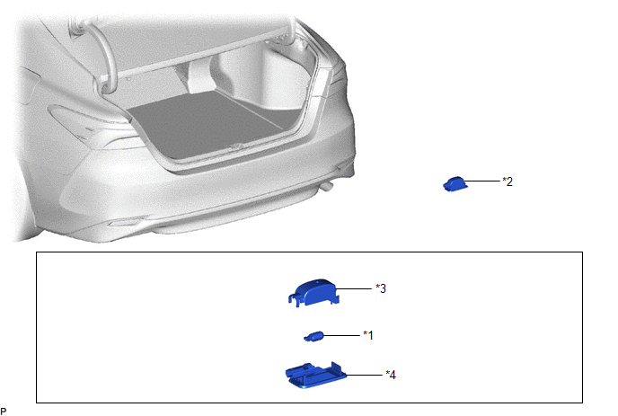
|
*1 | LUGGAGE COMPARTMENT LIGHT BULB |
*2 | NO. 1 LUGGAGE COMPARTMENT LIGHT ASSEMBLY |
|
*3 | SHADE |
*4 | NO. 1 LUGGAGE COMPARTMENT LIGHT LENS |
Removal
REMOVAL
PROCEDURE
1. REMOVE NO. 1 LUGGAGE COMPARTMENT LIGHT ASSEMBLY
| (a) Using a screwdriver with its tip wrapped with protective tape, disengage the claw. |
|
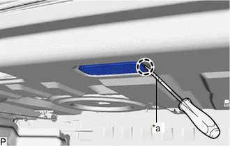
(b) Disconnect the connector to remove the No. 1 luggage compartment light assembly.
2. REMOVE LUGGAGE COMPARTMENT LIGHT BULB
| (a) Using a screwdriver with its tip wrapped with protective tape, disengage the 4 claws to remove the shade from the No. 1 luggage compartment light lens. |
|
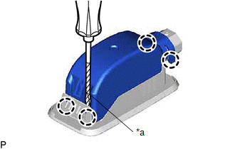
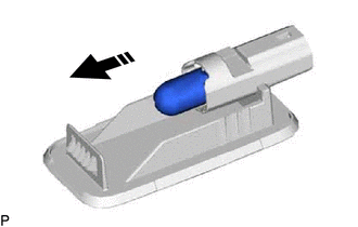
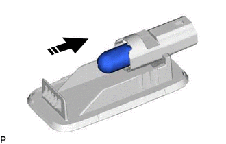
(b) Remove the luggage compartment light bulb from the No. 1 luggage compartment light lens as shown in the illustration.
 |
Remove in this Direction |
Inspection
INSPECTION
PROCEDURE
1. INSPECT NO. 1 LUGGAGE COMPARTMENT LIGHT ASSEMBLY
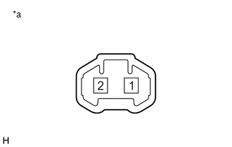
|
*a | Component without harness connected (No. 1 Luggage Compartment Light Assembly) |
(a) Apply battery voltage to the connector and check that the luggage compartment light comes on.
OK:
|
Measurement Condition | Condition |
Specified Condition |
|---|---|---|
|
Battery positive (+) > 1 Battery negative (-) > 2 |
Always | Luggage compartment light comes on |
If the result is not as specified, replace the bulb or No. 1 luggage compartment light assembly.
Installation
INSTALLATION
PROCEDURE
1. INSTALL LUGGAGE COMPARTMENT LIGHT BULB
(a) Install the luggage compartment light bulb to the No. 1 luggage compartment light lens as shown in the illustration.
 |
Install in this Direction |
| (b) Engage the 4 claws to install the shade to the No. 1 luggage compartment light lens. |
|
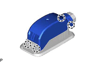
2. INSTALL NO. 1 LUGGAGE COMPARTMENT LIGHT ASSEMBLY
(a) Connect the connector.
| (b) Engage the claw to install the No. 1 luggage compartment light assembly. |
|
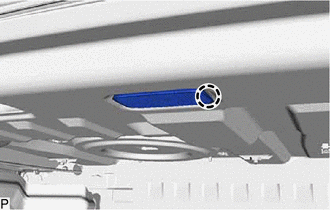
READ NEXT:
SEE MORE:
 No Answer-Back
DESCRIPTION In some cases, wireless door lock control functions are normal but the hazard warning light and wireless door lock buzzer answer-back functions do not operate. In such cases, hazard warning light and wireless door lock buzzer signal outputs from the main body ECU (multiplex network body
Installation
INSTALLATION PROCEDURE 1. INSTALL NO. 1 VACUUM SWITCHING VALVE ASSEMBLY (for ACIS)
(a) Install the No. 1 vacuum switching valve assembly (for ACIS) to the intake air surge tank assembly with the bolt.
Torque: 9.0 N·m {92 kgf·cm, 80 in·lbf} (b) Connect the 2 vacuum hose sub-assemblies to the
