Toyota Camry (XV70): Mirror Heater does not Operate with Rear Defogger Switch
DESCRIPTION
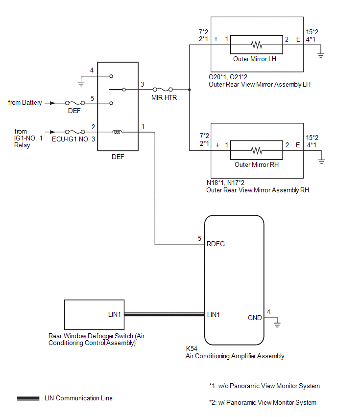
When the mirror heater switch (rear window defogger switch) on the air conditioning control assembly is pressed, the operation signal is sent to the air conditioning amplifier assembly via LIN communication. When the air conditioning amplifier assembly receives the signal, it turns on the DEF relay to operate the mirror heaters.
WIRING DIAGRAM
CAUTION / NOTICE / HINT
NOTICE:
- The power mirror control system uses the LIN communication system. Inspect the communication functions by following How to Proceed with Troubleshooting. Troubleshoot the power mirror control system after confirming that the communication systems are functioning properly.
- Inspect the fuses for circuits related to this system before performing the following procedure.
- If the battery voltage is low, the mirror heater function may not operate. In this case, check the Data List item "Battery Control Count (Body ECU)".
Click here
.gif)
PROCEDURE
|
1. | PERFORM ACTIVE TEST USING TECHSTREAM |
(a) Connect the Techstream to the DLC3.
(b) Turn the ignition switch to ON.
(c) Turn the Techstream on.
(d) Enter the following menus: Body Electrical / Air Conditioner / Active Test.
(e) Perform the Active Test according to the display on the Techstream.
Body Electrical > Air Conditioner > Active Test|
Tester Display | Measurement Item |
Control Range | Diagnostic Note |
|---|---|---|---|
|
Defogger Relay (Rear) |
Mirror Heater | OFF or ON |
- |
|
Tester Display |
|---|
|
Defogger Relay (Rear) |
|
Result | Proceed to |
|---|---|
|
Mirror heater operation on both mirrors is not normal |
A |
| Mirror heater operation on RH side mirror is not normal |
B |
| Mirror heater operation on LH side mirror is not normal |
C |
| B | .gif) |
GO TO STEP 4 |
| C | |
GO TO STEP 6 |
|
.gif)
|
2. | CHECK WINDOW DEFOGGER SYSTEM |
(a) Check the window defogger system operation.
Click here
OK:
The window defogger system operates normally.
| NG | |
GO TO WINDOW DEFOGGER SYSTEM |
|
|
3. | CHECK HARNESS AND CONNECTOR (DEF RELAY - OUTER REAR VIEW MIRROR ASSEMBLY RH/LH - BODY GROUND) |
(a) Remove the DEF relay from the engine room relay block and junction block assembly.
(b) Disconnect the N18*1 or N17*2 outer rear view mirror assembly RH connector.
(c) Disconnect the O20*1 or O21*2 outer rear view mirror assembly LH connector.
(d) Measure the resistance according to the value(s) in the table below.
Standard Resistance:
|
Tester Connection | Condition |
Specified Condition |
|---|---|---|
|
DEF relay holder terminal-3 - O20-2 (+)*1 or O21-7 (+)*2 |
Always | Below 1 Ω |
|
DEF relay holder terminal-3 - N18-2 (+)*1 or N17-7 (+)*2 |
Always | Below 1 Ω |
|
DEF relay holder terminal-3 - Body ground |
Always | 10 kΩ or higher |
- *1: w/o Panoramic View Monitor System
- *2: w/ Panoramic View Monitor System
| OK | |
USE SIMULATION METHOD TO CHECK
|
| NG | |
REPAIR OR REPLACE HARNESS OR CONNECTOR |
|
4. | CHECK HARNESS AND CONNECTOR (DEF RELAY - OUTER REAR VIEW MIRROR ASSEMBLY RH - BODY GROUND) |
(a) Remove the DEF relay from the engine room relay block and junction block assembly.
(b) Disconnect the N18*1 or N17*2 outer rear view mirror assembly RH connector.
(c) Disconnect the O20*1 or O21*2 outer rear view mirror assembly LH connector.
(d) Measure the resistance according to the value(s) in the table below.
Standard Resistance:
|
Tester Connection | Condition |
Specified Condition |
|---|---|---|
|
DEF relay holder terminal-3 - N18-2 (+)*1 or N17-7 (+)*2 |
Always | Below 1 Ω |
|
N18-4 (E)*1 or N17-15 (E)*2 - Body ground |
Always | Below 1 Ω |
|
N18-2 (+)*1 or N17-7 (+)*2 - Body ground |
Always | 10 kΩ or higher |
|
DEF relay holder terminal-3 - Body ground |
Always | 10 kΩ or higher |
- *1: w/o Panoramic View Monitor System
- *2: w/ Panoramic View Monitor System
| NG | |
REPAIR OR REPLACE HARNESS OR CONNECTOR |
|
|
5. | INSPECT OUTER MIRROR RH |
(a) Remove the outer mirror RH.
Click here
(b) Inspect the outer mirror RH.
Click here
OK:
Outer mirror RH is normal.
| OK | |
REPLACE OUTER REAR VIEW MIRROR ASSEMBLY RH |
| NG | |
REPLACE OUTER MIRROR RH |
|
6. | CHECK HARNESS AND CONNECTOR (DEF RELAY - OUTER REAR VIEW MIRROR ASSEMBLY LH - BODY GROUND) |
(a) Remove the DEF relay from the engine room relay block and junction block assembly.
(b) Disconnect the O20*1 or O21*2 outer rear view mirror assembly LH connector.
(c) Disconnect the N18*1 or N17*2 outer rear view mirror assembly RH connector.
(d) Measure the resistance according to the value(s) in the table below.
Standard Resistance:
|
Tester Connection | Condition |
Specified Condition |
|---|---|---|
|
DEF relay holder terminal-3 - O20-2 (+)*1 or O21-7 (+)*2 |
Always | Below 1 Ω |
|
O20-4 (E)*1 or O21-15 (E)*2 - Body ground |
Always | Below 1 Ω |
|
O20-2 (+)*1 or O21-7 (+)*2 - Body ground |
Always | 10 kΩ or higher |
|
DEF relay holder terminal-3 - Body ground |
Always | 10 kΩ or higher |
- *1: w/o Panoramic View Monitor System
- *2: w/ Panoramic View Monitor System
| NG | |
REPAIR OR REPLACE HARNESS OR CONNECTOR |
|
|
7. | INSPECT OUTER MIRROR LH |
(a) Remove the outer mirror LH.
Click here
(b) Inspect the outer mirror LH.
Click here
OK:
Outer mirror LH is normal.
| OK | |
REPLACE OUTER REAR VIEW MIRROR ASSEMBLY LH |
| NG | |
REPLACE OUTER MIRROR LH |
READ NEXT:
 Precaution
PRECAUTION PRECAUTION FOR DISCONNECTING CABLE FROM NEGATIVE BATTERY TERMINAL
NOTICE: When disconnecting the cable from the negative (-) battery terminal, initialize the following systems after the
SEE MORE:
Installation
INSTALLATION CAUTION / NOTICE / HINT
NOTICE:
Before replacing the main body ECU (multiplex network body ECU), refer to Registration.
w/ Smart Key System: Click here
w/o Smart Key System: Click here
After the main body ECU (multiplex network body ECU) has been replaced, the a
Remote Control System does not Operate
DESCRIPTION The main body ECU (multiplex network body ECU) receives remote control signals from the driver door key cylinder or electrical key transmitter sub-assembly. Then, the main body ECU (multiplex network body ECU) activates the power window motor and sends the remote control signals to the s
