Toyota Camry (XV70): Parts Location
PARTS LOCATION
ILLUSTRATION
|
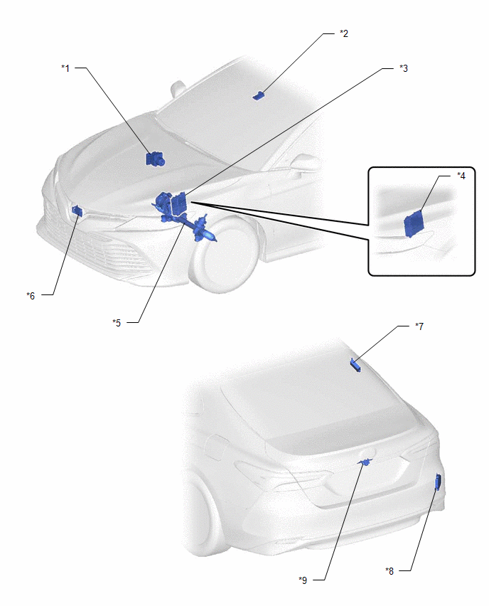
*1 | BRAKE ACTUATOR ASSEMBLY |
*2 | FORWARD RECOGNITION CAMERA (w/ Front Camera System) |
|
*3 | ECM (for A25A-FKS) |
*4 | ECM (for 2GR-FKS) |
|
*5 | RACK AND PINION POWER STEERING GEAR ASSEMBLY |
*6 | MILLIMETER WAVE RADAR SENSOR ASSEMBLY (w/ Front Camera System) |
|
*7 | TIRE PRESSURE WARNING ECU AND RECEIVER (for Tire Pressure Warning System with Tire Inflation Pressure Display Function) |
*8 | BLIND SPOT MONITOR SENSOR RH (w/ Blind Spot Monitor System) |
|
*9 | REAR TELEVISION CAMERA ASSEMBLY (w/ Parking Assist Monitor System or Panoramic View Monitor System) |
- | - |
ILLUSTRATION
|
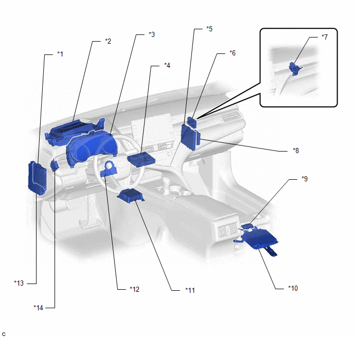
*1 | MAIN BODY ECU (MULTIPLEX NETWORK BODY ECU) |
*2 | METER MIRROR SUB-ASSEMBLY (w/ Headup Display System) |
|
*3 | COMBINATION METER ASSEMBLY |
*4 | DCM (TELEMATICS TRANSCEIVER) (w/ Telematics Transceiver) |
|
*5 | CERTIFICATION ECU (SMART KEY ECU ASSEMBLY) (w/ Smart Key System) |
*6 | CENTRAL GATEWAY ECU (NETWORK GATEWAY ECU) (w/ Smart Key System) |
|
*7 | CENTRAL GATEWAY ECU (NETWORK GATEWAY ECU) (w/o Smart Key System) |
*8 | CLEARANCE WARNING ECU ASSEMBLY (w/ Intuitive Parking Assist System) |
|
*9 | OCCUPANT DETECTION ECU |
*10 | TELEVISION CAMERA CONTROLLER (w/ Panoramic View Monitor System) |
|
*11 | AIRBAG SENSOR ASSEMBLY |
*12 | STEERING SENSOR |
|
*13 | INSTRUMENT PANEL JUNCTION BLOCK ASSEMBLY |
*14 | 4WD ECU ASSEMBLY (for AWD) |
ILLUSTRATION
|
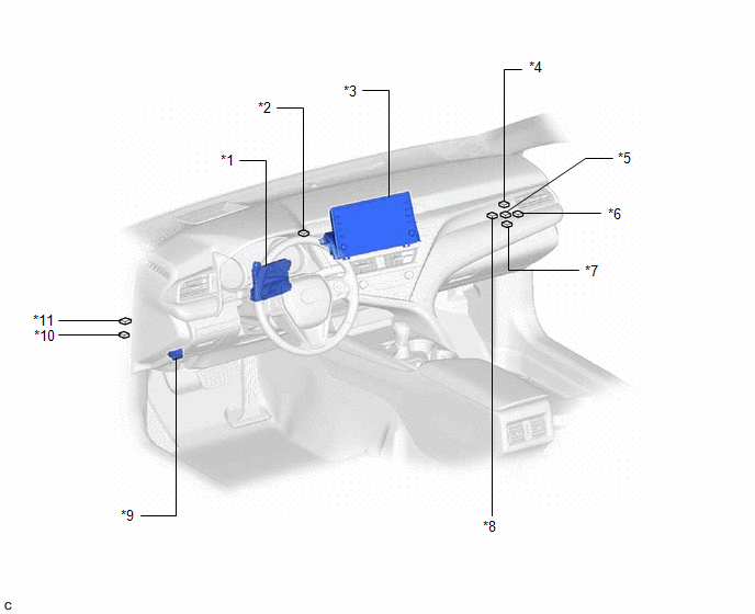
*1 | AIR CONDITIONING AMPLIFIER ASSEMBLY |
*2 | NO. 3 CAN JUNCTION CONNECTOR |
|
*3 | RADIO AND DISPLAY RECEIVER ASSEMBLY |
*4 | NO. 1 CAN JUNCTION CONNECTOR |
|
*5 | NO. 5 CAN JUNCTION CONNECTOR (w/ Parking Assist Monitor System or Panoramic View Monitor System) |
*6 | NO. 3 JUNCTION CONNECTOR |
|
*7 | NO. 2 JUNCTION CONNECTOR |
*8 | NO. 4 CAN JUNCTION CONNECTOR |
|
*9 | DLC3 |
*10 | NO. 1 JUNCTION CONNECTOR |
|
*11 | NO. 2 CAN JUNCTION CONNECTOR |
- | - |
READ NEXT:
 System Diagram
SYSTEM DIAGRAM (a) The CAN communication system is composed of 5 buses.
*A w/ Parking Assist Monitor System or Panoramic View Monitor System
*B w/ Rear View Monitor System
System Description
SYSTEM DESCRIPTION BRIEF DESCRIPTION (a) The Controller Area Network (CAN) is a serial data communication system for real time application. It is a vehicle multiplex communication system which has a h
How To Proceed With Troubleshooting
CAUTION / NOTICE / HINT PRECAUTIONS WHEN TROUBLESHOOTING
NOTICE:
Because the order of diagnosis is important to allow correct diagnosis, make sure to begin troubleshooting using How to Proceed w
SEE MORE:
Data List / Active Test
DATA LIST / ACTIVE TEST DATA LIST HINT:
Using the Techstream to read the Data List allows the values or states of switches, sensors, actuators and other items to be read without removing any parts. This non-intrusive inspection can be very useful because intermittent conditions or signals may be
Rear Speed Sensor
ComponentsCOMPONENTS ILLUSTRATION
*A w/o Electric Parking Brake System
- -
*1 PARKING BRAKE SHOE ADJUSTING HOLE PLUG
*2 REAR AXLE HUB AND BEARING ASSEMBLY
*3 REAR DISC
*4 REAR DISC BRAKE CALIPER ASSEMBLY
*5 SKID CONTROL SENSOR WIRE
