Toyota Camry (XV70): System Description
SYSTEM DESCRIPTION
BRIEF DESCRIPTION
(a) The Controller Area Network (CAN) is a serial data communication system for real time application. It is a vehicle multiplex communication system which has a high communication speed and the ability to detect malfunctions.
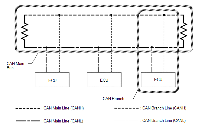
(b) Using the CANH and CANL bus lines as a pair, CAN communication is performed using a voltage differential. (A base voltage is applied to the pair of lines and a voltage differential is created when communicating.)
(c) Many ECUs or sensors installed to the vehicle operate by sharing information and communicating with each other.
(d) 2 resistors which are necessary for communication are used in a CAN bus main line.
DEFINITION OF TERMS
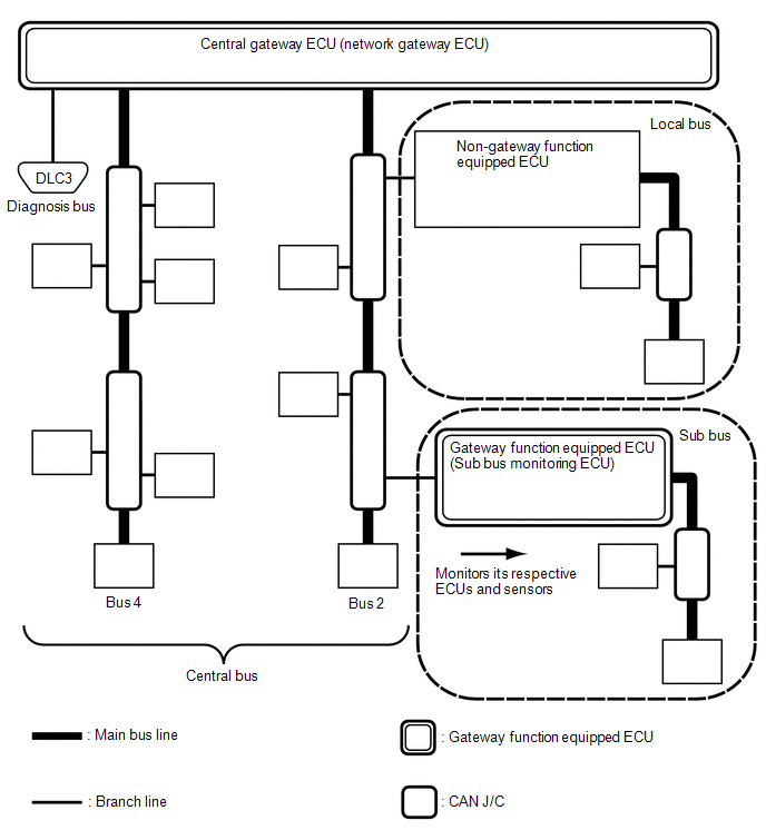
(a) Central bus
(1) The central bus is a term used to describe all buses directly connected to the central gateway ECU (network gateway ECU).
HINT:
A bus is displayed as Bus on the "Communication Bus Check" screen of the Techstream.
(b) Sub bus
(1) A sub bus is a bus that has a gateway function equipped ECU in order to communicate with the central bus and other sub buses.
HINT:
- A sub bus is displayed as Sub bus on the "Communication Bus Check" screen of the Techstream.
- When Sub bus is selected on the "Communication Bus Check" screen, ECUs and sensors connected to non-CAN networks such as LIN may also be displayed in addition to the ECUs and sensors connected to sub buses in the CAN network.
(c) Local bus
(1) A local bus is a bus that does not have the ability to communicate with other buses. ECUs and sensors on a local bus can only communicate with other ECUs and sensors on the same bus.
(d) CAN J/C
(1) A CAN junction connector is a connector that connects branch lines to a main bus.
(e) Main bus
(1) A main bus line is the wire harness that runs between the 2 terminating resistors of a bus.
(f) Branch
(1) A branch line is a wire harness that connects an ECU or sensor to a main bus line.
(g) Terminating resistors
(1) Terminating resistors which maintain a stable signal inside the CAN bus are installed. 2 resistors of 120 Ω each located at each end of the bus are necessary.
READ NEXT:
 How To Proceed With Troubleshooting
CAUTION / NOTICE / HINT PRECAUTIONS WHEN TROUBLESHOOTING
NOTICE:
Because the order of diagnosis is important to allow correct diagnosis, make sure to begin troubleshooting using How to Proceed w
Utility
UTILITY INITIALIZE THE CONNECTION INFORMATION OF A GATEWAY FUNCTION EQUIPPED ECU (BUS MONITOR ECU)
(a) Connect the Techstream to the DLC3. (b) Turn the ignition switch to ON.
(c) Turn the Techstre
Problem Symptoms Table
PROBLEM SYMPTOMS TABLE
HINT:
Use the table below to help determine the cause of problem symptoms.
Inspect the fuses and relays related to this system before inspecting the suspected areas b
SEE MORE:
Components
COMPONENTS ILLUSTRATION
*1 ENGINE OIL LEVEL SENSOR
*2 NO. 2 OIL PAN SUB-ASSEMBLY
*3 OIL STRAINER SUB-ASSEMBLY
*4 OIL STRAINER GASKET
N*m (kgf*cm, ft.*lbf): Specified torque
● Non-reusable part
Reassembly
REASSEMBLY CAUTION / NOTICE / HINT
HINT:
Use the same procedure for the RH side and LH side.
The following procedure is for the LH side.
PROCEDURE 1. INSTALL REAR COMBINATION LIGHT LENS AND BODY (for Bulb Type Back-up Light)
2. INSTALL REAR COMBINATION LIGHT SOCKET AND WIRE (fo
