Toyota Camry (XV70): Parts Location
Toyota Camry Repair Manual XV70 (2018-2024) / Steering / Steering Column / Heated Steering Wheel System / Parts Location
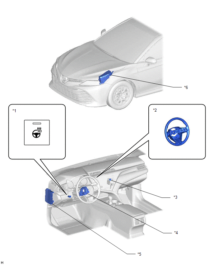
PARTS LOCATION
ILLUSTRATION
|
*1 | STEERING HEATER SWITCH |
*2 | STEERING WHEEL ASSEMBLY |
|
*3 | NO. 6 RELAY BLOCK - STRG HTR RELAY |
*4 | SPIRAL CABLE SUB-ASSEMBLY |
|
*5 | INSTRUMENT PANEL JUNCTION BLOCK ASSEMBLY - ECU-IG1 NO. 3 FUSE |
*6 | ENGINE ROOM RELAY BLOCK AND JUNCTION BLOCK ASSEMBLY - STRG HTR FUSE |
READ NEXT:
 System Diagram
SYSTEM DIAGRAM SYSTEM DIAGRAM
System Description
SYSTEM DESCRIPTION HEATED STEERING WHEEL SYSTEM
(a) The steering heater warms up the steering wheel when the steering heater switch is turned on.
(b) The steering heater uses a control thermosta
How To Proceed With Troubleshooting
CAUTION / NOTICE / HINT HINT: Use these procedures to troubleshoot the heated steering wheel system. PROCEDURE
1. VEHICLE BROUGHT TO WORKSHOP
NEXT
SEE MORE:
Ultrasonic Sensor (Front Right Corner) Missing Message (C1AE487)
DESCRIPTION This DTC is stored when an open circuit or short occurs in the communication line between the front corner ultrasonic sensor RH and the clearance warning ECU, or when a malfunction occurs in the front corner ultrasonic sensor RH.
DTC No. Detection Item
DTC Detection Conditio
Installation
INSTALLATION CAUTION / NOTICE / HINT
NOTICE:
Immediately after installing the brake pads, the braking performance may be reduced. Always perform a road test in a safe place while paying attention to the surroundings.
After replacing the front disc brake pads, always perform a road test to
© 2023-2026 Copyright www.tocamry.com
