
Toyota Camry (XV70): Parts Location
Toyota Camry Repair Manual XV70 (2018-2024) / Vehicle Exterior / Mirror (ext) / Power Mirror Control System / Parts Location
PARTS LOCATION
ILLUSTRATION
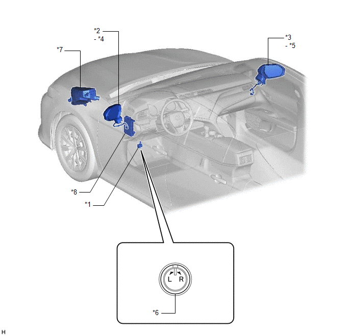
|
*1 | OUTER MIRROR SWITCH ASSEMBLY |
*2 | OUTER REAR VIEW MIRROR ASSEMBLY LH |
|
*3 | OUTER REAR VIEW MIRROR ASSEMBLY RH |
*4 | OUTER MIRROR LH |
|
*5 | OUTER MIRROR RH |
*6 | MIRROR SELECT AND SURFACE ADJUST SWITCH |
|
*7 | ENGINE ROOM RELAY BLOCK AND JUNCTION BLOCK ASSEMBLY - DEF FUSE - DEF RELAY - MIR HTR FUSE |
*8 | INSTRUMENT PANEL JUNCTION BLOCK ASSEMBLY - ECU-ACC FUSE - ECU-IG1 NO. 3 FUSE |
ILLUSTRATION
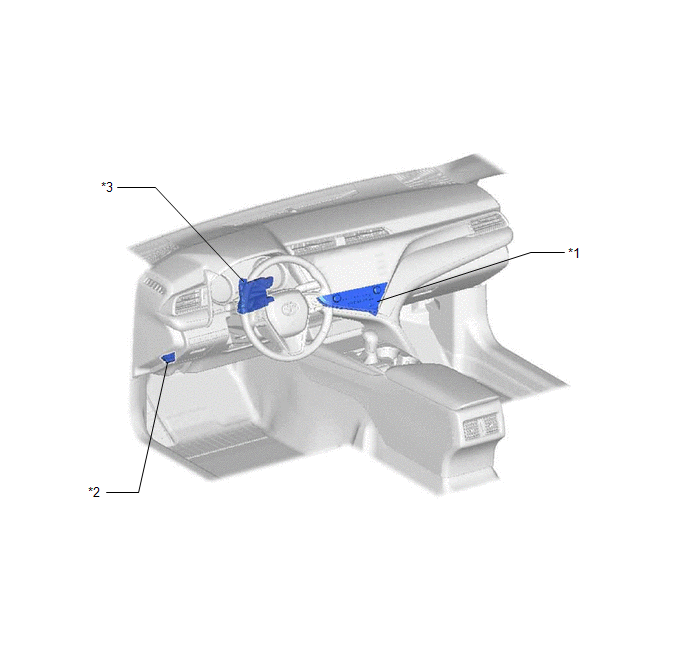
|
*1 | REAR WINDOW DEFOGGER SWITCH (AIR CONDITIONING CONTROL ASSEMBLY) |
*2 | DLC3 |
|
*3 | AIR CONDITIONING AMPLIFIER ASSEMBLY |
- | - |
READ NEXT:
 System Diagram
SYSTEM DIAGRAM ELECTRICAL REMOTE CONTROL MIRROR FUNCTION
MIRROR HEATER FUNCTION
Communication Table
Sender Receiver
Signal Communication Method
Air Conditioning C
System Description
SYSTEM DESCRIPTION POWER MIRROR CONTROL SYSTEM DESCRIPTION
(a) This system has the following functions: electrical remote control mirror function and mirror heater function.
FUNCTION OF MAIN COM
How To Proceed With Troubleshooting
CAUTION / NOTICE / HINT
HINT:
Use the following procedure to troubleshoot the power mirror control system
*: Use the Techstream.
PROCEDURE
1. VEHICLE BROUGHT TO WORKSHOP
SEE MORE:
Fail-safe Chart
FAIL-SAFE CHART FAIL-SAFE CHART (a) When the skid control ECU (brake actuator assembly) detects a solenoid valve malfunction or abnormal signal from a sensor, the brake actuator assembly cuts power and sends a signal indicating a malfunction of the vehicle stability control system to the ECM.
HINT
Problem Symptoms Table
PROBLEM SYMPTOMS TABLE
HINT:
Use the table below to help determine the cause of problem symptoms. If multiple suspected areas are listed, the potential causes of the symptoms are listed in order of probability in the "Suspected Area" column of the table. Check each symptom by checking the suspect
© 2023-2026 Copyright www.tocamry.com
