
Toyota Camry (XV70): System Diagram
Toyota Camry Repair Manual XV70 (2018-2024) / Vehicle Exterior / Mirror (ext) / Power Mirror Control System / System Diagram
SYSTEM DIAGRAM
ELECTRICAL REMOTE CONTROL MIRROR FUNCTION
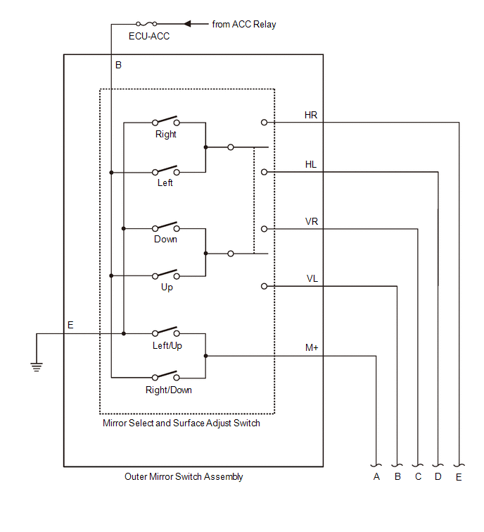
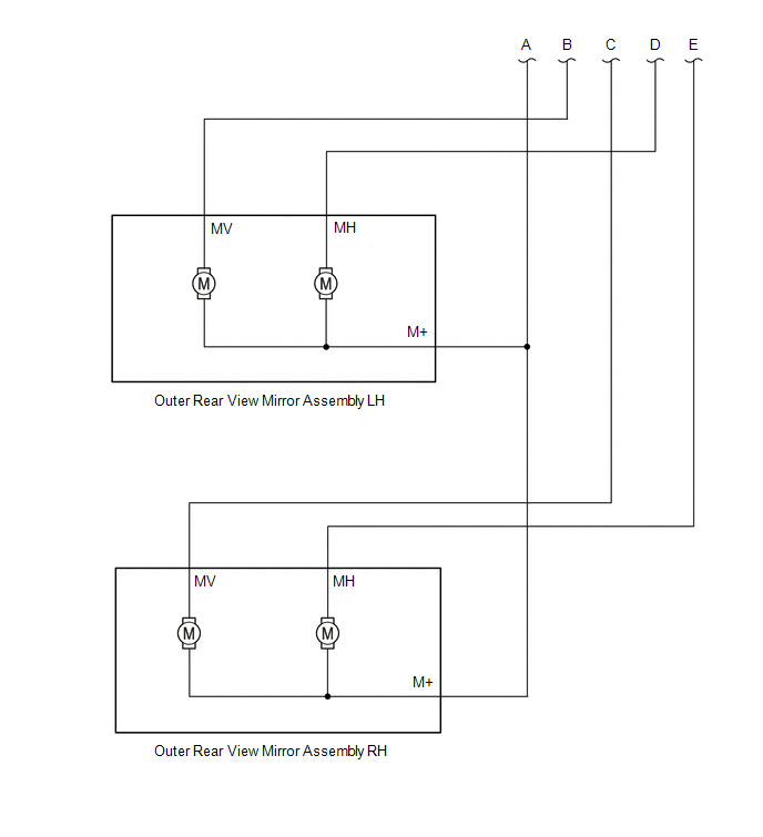
MIRROR HEATER FUNCTION
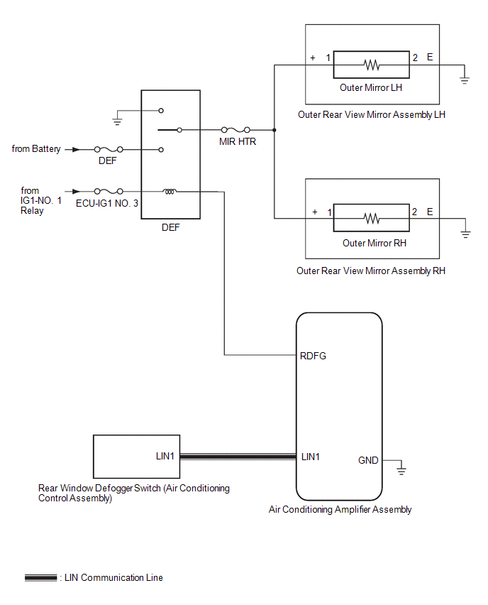 Communication Table
 |
Sender | Receiver |
Signal | Communication Method |
|---|---|---|---|
|
Air Conditioning Control Assembly |
Air Conditioning Amplifier Assembly |
Mirror heater switch (rear window defogger switch) signal |
LIN |
READ NEXT:
 System Description
SYSTEM DESCRIPTION POWER MIRROR CONTROL SYSTEM DESCRIPTION
(a) This system has the following functions: electrical remote control mirror function and mirror heater function.
FUNCTION OF MAIN COM
How To Proceed With Troubleshooting
CAUTION / NOTICE / HINT
HINT:
Use the following procedure to troubleshoot the power mirror control system
*: Use the Techstream.
PROCEDURE
1. VEHICLE BROUGHT TO WORKSHOP
Operation Check
OPERATION CHECK CHECK ELECTRICAL REMOTE CONTROL MIRROR FUNCTION
(a) Turn the ignition switch to ON. (b) With L on the mirror select switch selected, check that the outer rear view mirror assembly L
SEE MORE:
XM Tuner Antenna Disconnected (B15FE,B15FF)
DESCRIPTION These DTCs are stored when a malfunction occurs in the roof antenna assembly which is connected to the radio and display receiver assembly.
DTC No. Detection Item
DTC Detection Condition Trouble Area
B15FE XM Tuner Antenna Disconnected
The roof antenna asse
Blind Spot Monitor Slave Module (C1AB7)
DESCRIPTION This DTC is stored when the blind spot monitor sensor LH detects an internal malfunction.
DTC No. Detection Item
DTC Detection Condition Trouble Area
C1AB7 Blind Spot Monitor Slave Module
The blind spot monitor sensor LH (slave) detects an internal malfunct
© 2023-2026 Copyright www.tocamry.com
