
Toyota Camry (XV70): Power Window Master Switch
Components
COMPONENTS
ILLUSTRATION
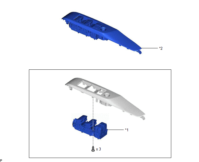
|
*1 | MULTIPLEX NETWORK MASTER SWITCH ASSEMBLY |
*2 | MULTIPLEX NETWORK MASTER SWITCH ASSEMBLY WITH FRONT DOOR UPPER ARMREST BASE PANEL |
Removal
REMOVAL
PROCEDURE
1. REMOVE MULTIPLEX NETWORK MASTER SWITCH ASSEMBLY WITH FRONT DOOR UPPER ARMREST BASE PANEL
(a) Apply protective tape to the front door trim board sub-assembly as shown in the illustration.
.png)
.png) |
Protective Tape |
(b) Disengage the 3 clips, 15 claws and 8 guides as shown in the illustration.
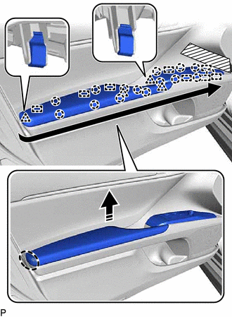
.png) |
Place Hand Here |
.png) |
Remove in this Direction |
.png) |
Order of Removal |
(c) Disengage the guide as shown in the illustration.
.png)
|
|
Remove in this Direction |
(d) Disconnect the connector to remove the multiplex network master switch assembly with front door upper armrest base panel.
(e) Engage the 3 clips, 8 claws and 3 guides to install the front armrest assembly as shown in the illustration.
.png)
|
|
Install in this Direction |
2. REMOVE MULTIPLEX NETWORK MASTER SWITCH ASSEMBLY
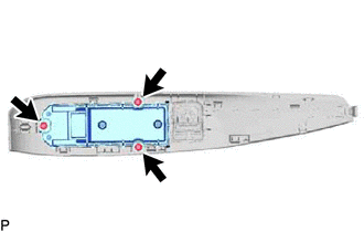
| (a) Remove the 3 screws and multiplex network master switch assembly. |
|
Inspection
INSPECTION
PROCEDURE
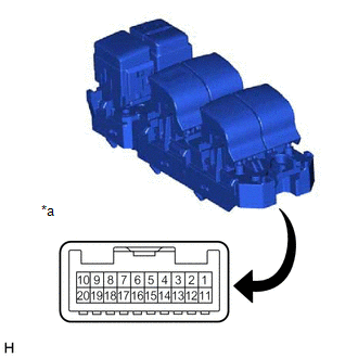
1. INSPECT MULTIPLEX NETWORK MASTER SWITCH ASSEMBLY
| (a) Check that the LED illuminates. (1) Apply battery voltage to the multiplex network master switch assembly and check that the LED illuminates. OK:
If the result is not as specified, replace the multiplex network master switch assembly. |
|
Installation
INSTALLATION
PROCEDURE
1. INSTALL MULTIPLEX NETWORK MASTER SWITCH ASSEMBLY
(a) Install the multiplex network master switch assembly with the 3 screws.
2. INSTALL MULTIPLEX NETWORK MASTER SWITCH ASSEMBLY WITH FRONT DOOR UPPER ARMREST BASE PANEL
Click here .gif)
READ NEXT:
 Components
COMPONENTS ILLUSTRATION
*A w/o Courtesy Light
*B w/ Courtesy Light
*C for Front Passenger Side
*D for Driver Side
*1 COURTESY LIGHT ASSEMBLY
Removal
REMOVAL CAUTION / NOTICE / HINT
The necessary procedures (adjustment, calibration, initialization or registration) that must be performed after parts are removed and installed, or replaced during p
SEE MORE:
Components
COMPONENTS ILLUSTRATION
*1 FRONT FENDER APRON SEAL RH
*2 V-BANK COVER SUB-ASSEMBLY
N*m (kgf*cm, ft.*lbf): Specified torque
- - ILLUSTRATION
*1 CAMSHAFT TIMING OIL CONTROL SOLENOID ASSEMBLY (for Intake Side of Bank 1)
*2 CAMSHAFT TIMIN
Initialization
INITIALIZATION INITIALIZE SLIDING ROOF SYSTEM
NOTICE:
When the sliding roof glass sub-assembly or sliding roof drive cable sub-assembly is adjusted or removed/installed, or the sliding roof drive gear sub-assembly is replaced, the sliding roof ECU (sliding roof drive gear sub-assembly) must
