Toyota Camry (XV70): Reassembly
REASSEMBLY
PROCEDURE
1. INSTALL SUNSHADE TRIM SUB-ASSEMBLY
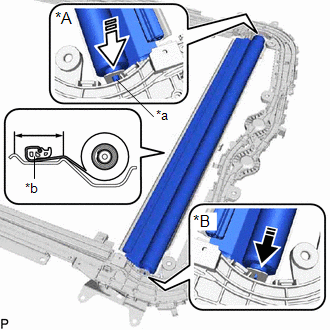
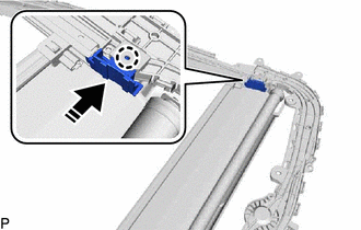
(a) Install the sunshade trim sub-assembly as shown in the illustration.
|
*A | RH Side |
|
*B | LH Side |
|
*a | Retractor Cap |
|
*b | Portion A |
.png) |
Install in this Direction (1) |
.png) |
Install in this Direction (2) |
NOTICE:
To prevent the sunshade trim sub-assembly from being damaged, fully push in the RH side retractor cap when installing the sunshade trim sub-assembly.
HINT:
- Connect the LH side first.
- Set the portion (A) within the area shown in the illustration when installing the sunshade trim sub-assembly.
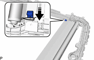
(b) Insert the sliding roof sunshade runner into the sunshade trim sub-assembly as shown in the illustration.
|
|
Install in this Direction |
HINT:
Use the same procedure for the RH side and LH side.
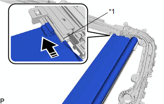
(c) Slide the sliding roof sunshade runner and sunshade trim sub-assembly as shown in the illustration to install them to the sliding roof guide rail sub-assembly RH.
|
*1 | Sliding Roof Guide Rail Sub-assembly RH |
|
|
Install in this Direction |
HINT:
Use the same procedure for the RH side and LH side.
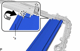
(d) Move the portion (A) as shown in the illustration to engage the claw.
|
*a | Portion A |
|
|
Install in this Direction |
HINT:
Use the same procedure for the RH side and LH side.
(e) Engage the claw to install the sliding roof sunshade guide RH as shown in the illustration.
HINT:
Use the same procedure for the RH side and LH side.
|
|
Install in this Direction |
2. INSTALL SLIDE ROOF RAIL SUB-ASSEMBLY
(a) Install the slide roof rail sub-assembly with the 42 nuts.
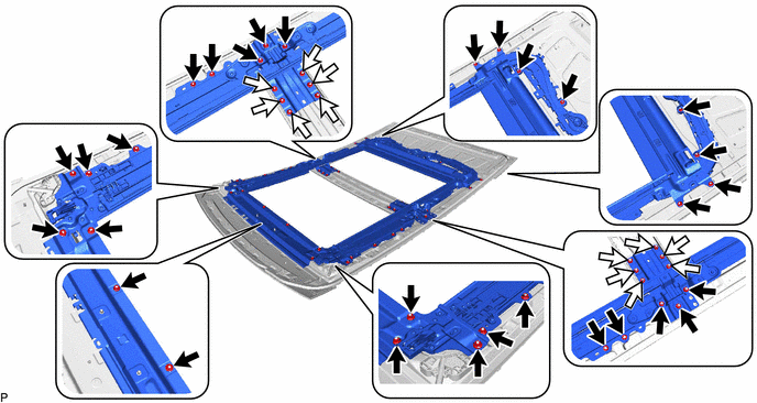
.png) |
Nut (A) |
.png) |
Nut (B) |
Torque:
Nut (A) :
6.2 N
READ NEXT:
 Installation
INSTALLATION PROCEDURE 1. INSTALL SLIDING ROOF HOUSING ASSEMBLY
(a) Pass a string under the windshield outside moulding as shown in the illustration.
*1 Windshield Outside Moulding
Components
COMPONENTS ILLUSTRATION
*1 ROOF CONSOLE BOX ASSEMBLY
*2 ROOF CONSOLE BOX SUB-ASSEMBLY
*3 TELEPHONE MICROPHONE ASSEMBLY
- -
SEE MORE:
Blind Spot Monitor Sensor Communication Stop Mode
DESCRIPTION
Detection Item Symptom
Trouble Area Blind Spot Monitor Sensor Communication Stop Mode
Any of the following conditions are met:
Communication stop for "Blind Spot Monitor Master" is indicated on the "Communication Bus Check" screen of the Techstream.
Cl
Software Incompatibility with Body Control Module Not Programmed (U032251)
DESCRIPTION The forward recognition camera receives vehicle information from the main body ECU (multiplex network body ECU) via CAN communication.
DTC U032251 is stored when the forward recognition camera cannot confirm the vehicle information from the main body ECU (multiplex network body ECU).
