
Toyota Camry (XV70): Reassembly
REASSEMBLY
PROCEDURE
1. INSTALL NO. 1 COOLER THERMISTOR
Click here .gif)
2. INSTALL NO. 1 COOLER EVAPORATOR SUB-ASSEMBLY
| (a) Install the No. 1 cooler evaporator sub-assembly with No. 1 cooler thermistor to the upper heater case. NOTICE: When the No. 1 cooler evaporator sub-assembly is removed, make sure to install a new one. The No. 1 cooler evaporator sub-assembly cannot be reused. |
|
.png)
(b) Engage the clamp.
(c) Engage the 10 claws to install the upper heater case with No. 1 cooler evaporator sub-assembly to the lower heater case.
.png)
(d) Install the 2 screws.
3. INSTALL COOLER EXPANSION VALVE
(a) Sufficiently apply compressor oil to 2 new O-rings and the fitting surfaces of the No. 1 cooler evaporator sub-assembly.
Compressor Oil:
ND-OIL 12 or equivalent
(b) Install the 2 O-rings to the No. 1 cooler evaporator sub-assembly.
NOTICE:
Keep the O-rings and O-ring fitting surfaces free of foreign matter.
| (c) Using a 4 mm hexagon socket wrench, install the cooler expansion valve with the 2 hexagon bolts. Torque: 3.5 N·m {36 kgf·cm, 31 in·lbf} |
|
.png)
4. INSTALL GROMMET SUB-ASSEMBLY
| (a) Install the grommet sub-assembly. |
|
.png)
5. INSTALL HEATER RADIATOR UNIT SUB-ASSEMBLY
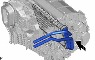
.png) |
Install in this Direction |
(a) Install the heater radiator unit sub-assembly as shown in the illustration.
6. INSTALL HEATER CLAMP
|
(a) Engage the 3 claws to install the heater clamp. |
|
.png)
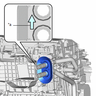
7. INSTALL HEATER PIPE GROMMET
| (a) Install the heater pipe grommet as shown in the illustration. NOTICE: Install the heater pipe grommet with the arrow facing up. |
|
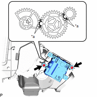
8. INSTALL NO. 2 AIR CONDITIONING RADIATOR DAMPER SERVO SUB-ASSEMBLY (for Dual Type)
| (a) Using the reference points, install the No. 2 air conditioning radiator damper servo sub-assembly with the 2 screws. |
|
9. INSTALL NO. 1 AIR CONDITIONING RADIATOR DAMPER SERVO SUB-ASSEMBLY
(a) for Single Type:
(1) Align each gear on the air conditioning radiator assembly as shown in the illustration, and then check that the gears of the No. 1 air conditioning radiator damper servo sub-assembly are aligned as shown in the illustration.
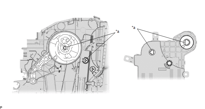
|
*a | Reference Point |
- | - |
| (2) Install the No. 1 air conditioning radiator damper servo sub-assembly with the 3 screws. |
|
.png)
(b) for Dual Type:
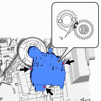
(1) Align each gear on the air conditioning radiator assembly as shown in the illustration, and then check that the gears of the No. 1 air conditioning radiator damper servo sub-assembly are aligned as shown in the illustration.
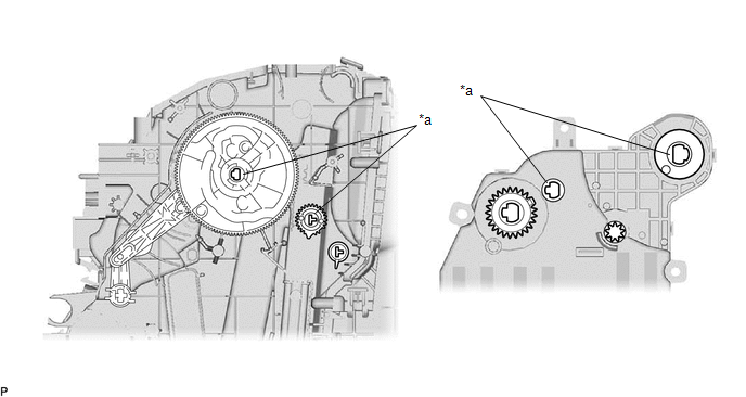
|
*a | Reference Point |
- | - |
| (2) Using the reference points, install the No. 1 air conditioning radiator damper servo sub-assembly with the 3 screws. |
|
10. INSTALL DRAIN COOLER HOSE
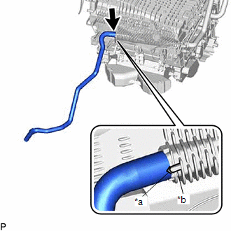
| (a) Align the hose notch with the rib as shown in the illustration and install the drain cooler hose. |
|
11. INSTALL HEATER COVER
|
|
Install in this Direction |
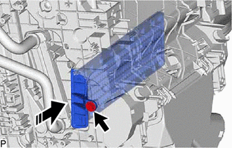
(a) Install the heater cover as shown in the illustration.
(b) Install the screw.
12. INSTALL AIR CONDITIONING HARNESS ASSEMBLY
(a) for Single Type:
| (1) Engage each clamp. |
|
.png)
(2) Connect each connector to install the air conditioning harness assembly.
(b) for Dual Type:
| (1) Engage each clamp. |
|
.png)
(2) Connect each connector to install the air conditioning harness assembly.
13. INSTALL AIR CONDITIONING AMPLIFIER ASSEMBLY
(a) Engage the guide to temporarily install the air conditioning amplifier assembly as shown in the illustration.
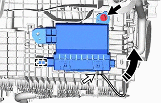
|
|
Install in this Direction |
(b) Install the air conditioning amplifier assembly with the screw.
(c) Connect the connector.
14. INSTALL BLOWER ASSEMBLY
Click here
15. INSTALL GROMMET (for Manual Air Conditioning System)
| (a) Engage the 2 claws to install the grommet. |
|
.png)
16. INSTALL ASPIRATOR (for Automatic Air Conditioning System)
| (a) Engage the 2 claws and guide to install the aspirator. |
|
.png)
17. INSTALL NO. 2 AIR DUCT
| (a) Engage the 3 claws. |
|
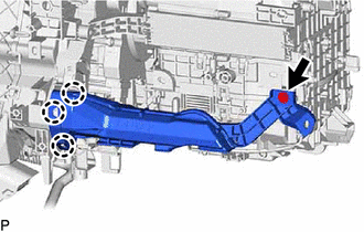
(b) Install a new No. 2 air duct with the screw.
18. INSTALL NO. 2 AIR DUCT SUB-ASSEMBLY
| (a) Engage the 4 claws to install the No. 2 air duct sub-assembly. |
|
.png)
19. INSTALL NO. 3 AIR DUCT SUB-ASSEMBLY
| (a) Engage the 4 claws. |
|
.png)
| (b) Install the No. 3 air duct sub-assembly with the 2 screws. |
|
.png)
READ NEXT:
 Installation
INSTALLATION PROCEDURE 1. TEMPORARILY INSTALL AIR CONDITIONER UNIT ASSEMBLY
(a) w/ Claw: (1) Engage the 2 claws. (b) Temporarily install the air conditioner unit assembly to the instrument panel rein
Ambient Temperature Sensor
ComponentsCOMPONENTS ILLUSTRATION
*A for Bar Type Radiator Grille
*B for Mesh Type Radiator Grille
*1 FRONT RADIATOR SIDE AIR GUIDE PLATE RH
*2 THERMISTOR ASSEMBLY R
SEE MORE:
Installation
INSTALLATION PROCEDURE 1. TEMPORARILY INSTALL FUEL (ENGINE ROOM SIDE) PUMP ASSEMBLY
(a) Turn the crankshaft pulley until the flat of the camshaft faces the fuel pump lifter assembly.
HINT: This prevents the camshaft nose from pushing up the fuel pump lifter assembly when installing the fuel
Torque Converter And Drive Plate
InspectionINSPECTION PROCEDURE
1. INSPECT TORQUE CONVERTER ASSEMBLY (a) Inspect the one-way clutch. Press on the splines of the stator with a finger and rotate it. Check that it rotates smoothly when turned clockwise and rotates with difficulty when turned counterclockwise.
Diffic
