
Toyota Camry (XV70): Ambient Temperature Sensor
Components
COMPONENTS
ILLUSTRATION
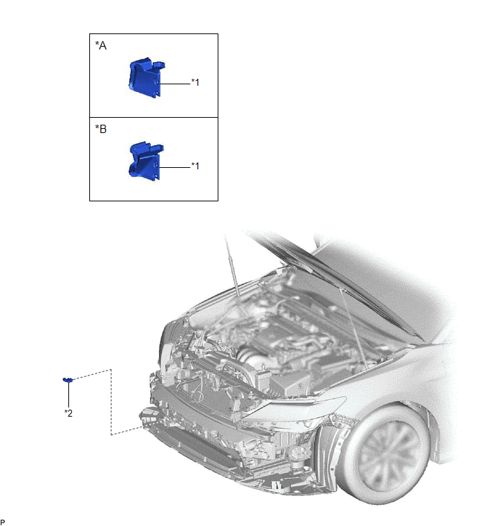
|
*A | for Bar Type Radiator Grille |
*B | for Mesh Type Radiator Grille |
|
*1 | FRONT RADIATOR SIDE AIR GUIDE PLATE RH |
*2 | THERMISTOR ASSEMBLY |
Removal
REMOVAL
CAUTION / NOTICE / HINT
The necessary procedures (adjustment, calibration, initialization, or registration) that must be performed after parts are removed and installed, or replaced during thermistor assembly removal/installation are shown below.
Necessary Procedure After Parts Removed/Installed/Replaced|
Replaced Part or Performed Procedure |
Necessary Procedure | Effect/Inoperative Function when Necessary Procedure not Performed |
Link |
|---|---|---|---|
| Front bumper assembly (w/ Panoramic view monitor system) |
Front television camera view adjustment |
Panoramic View Monitor System |
|
PROCEDURE
1. REMOVE FRONT BUMPER ASSEMBLY
Click here
.gif)
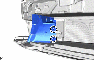
2. REMOVE FRONT RADIATOR SIDE AIR GUIDE PLATE RH
| (a) Disengage the 2 claws to remove the front radiator side air guide plate RH. |
|
3. REMOVE THERMISTOR ASSEMBLY
| (a) Disengage the clamp. |
|
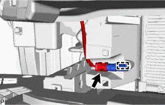
(b) Disconnect the connector to remove the thermistor assembly.
Inspection
INSPECTION
PROCEDURE
1. INSPECT THERMISTOR ASSEMBLY
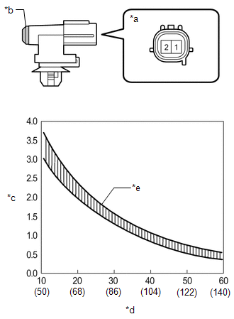
| (a) Measure the resistance according to the value(s) in the table below. Standard Resistance:
NOTICE:
HINT: As the temperature increases, the resistance decreases (see the graph). If the result is not as specified, replace the thermistor assembly. |
|
Installation
INSTALLATION
PROCEDURE
1. INSTALL THERMISTOR ASSEMBLY
(a) Connect the connector.
(b) Engage the clamp to install the thermistor assembly.
2. INSTALL FRONT RADIATOR SIDE AIR GUIDE PLATE RH
(a) Engage the 2 claws to install the front radiator side air guide plate RH.
3. INSTALL FRONT BUMPER ASSEMBLY
Click here
.gif)
READ NEXT:
 Components
COMPONENTS ILLUSTRATION
*1 AIR FILTER COVER PLATE
*2 BLOWER ASSEMBLY
*3 BLOWER MOTOR WITH FAN SUB-ASSEMBLY
*4 CLEAN AIR FILTER
*5 NO. 1 BLOWER DAMPER SERVO SUB
Removal
REMOVAL CAUTION / NOTICE / HINT
The necessary procedures (adjustment, calibration, initialization or registration) that must be performed after parts are removed and installed, or replaced during blo
SEE MORE:
Data List / Active Test
DATA LIST / ACTIVE TEST DATA LIST NOTICE:
In the table below, the values listed under "Normal Condition" are reference values. Do not depend solely on these reference values when deciding whether a part is faulty or not.
HINT: Using the Techstream to read the Data List allows the values or sta
USB Audio System Recognition/Play Error
DESCRIPTION When a USB device or "iPod" is connected to the USB jack of the No. 1 stereo jack adapter assembly, it must have playable files. The device must also communicate with and be recognized by the radio and display receiver assembly. This diagnostic procedure is for when a device is not recog
