
Toyota Camry (XV70): Removal
REMOVAL
CAUTION / NOTICE / HINT
The necessary procedures (adjustment, calibration, initialization or registration) that must be performed after parts are removed and installed, or replaced during blower unit removal/installation are shown below.
Necessary Procedure After Parts Removed/Installed/Replaced|
Replaced Part or Performed Procedure |
Necessary Procedure | Effect/Inoperative Function when Necessary Procedure not Performed |
Link |
|---|---|---|---|
|
Disconnect cable from negative battery terminal |
Perform steering sensor zero point calibration |
Lane Tracing Assist System |
|
|
Pre-collision System | |||
|
Memorize steering angle neutral point |
Parking Assist Monitor System |
| |
|
Panoramic View Monitor System |
| ||
|
Steering sensor |
| Parking assist monitor system |
|
CAUTION:
Some of these service operations affect the SRS airbag system. Read the precautionary notices concerning the SRS airbag system before servicing.
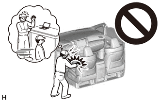
Click here

HINT:
Before removing the blower assembly, set the air conditioning to recirculation mode.
PROCEDURE
1. REMOVE AIR CONDITIONER UNIT ASSEMBLY
Click here
2. REMOVE NO. 2 AIR DUCT
Click here
3. REMOVE BLOWER ASSEMBLY
| (a) Disconnect the connector. |
|
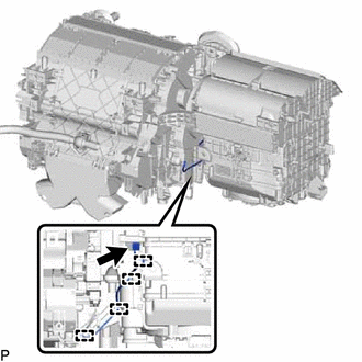
(b) Disengage each guide.
| (c) Remove the 2 screws. |
|
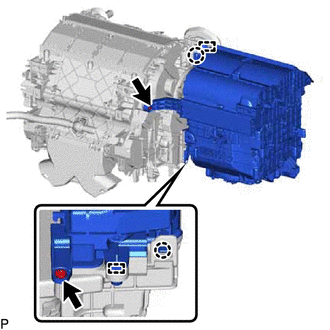
(d) Disengage the 2 claws and 2 guides and remove the blower assembly from the air conditioning radiator assembly.
READ NEXT:
 Disassembly
DISASSEMBLY PROCEDURE 1. REMOVE AIR FILTER COVER PLATE
(a) Disengage the claw and 2 guides as indicated by the arrows, in the order shown in the illustration to remove the air filter cover plate.
Reassembly
REASSEMBLY PROCEDURE 1. INSTALL NO. 1 BLOWER DAMPER SERVO SUB-ASSEMBLY
(a) Connect the 2 links of the blower assembly to the 2 grooves on the plate of the No. 1 blower damper servo sub-assembly a
Installation
INSTALLATION PROCEDURE 1. INSTALL BLOWER ASSEMBLY
(a) Engage the 2 guides and 2 claws. (b) Install the blower assembly to the air conditioning radiator assembly with the 2 screws.
(c) Engage each gu
SEE MORE:
Internal Control Module A/D Processing Performance Internal Electronic Failure (P060B49)
MONITOR DESCRIPTION This DTC is stored when a communication error occurs in the ECM.
DTC No. Detection Item
DTC Detection Condition Trouble Area
MIL Memory
Note P060B49
Internal Control Module A/D Processing Performance Internal Electronic Failure
ECM main
Engine (ignition) switch
(vehicles with a
smart key system)
Performing the following operations when carrying the electronic
key on your person starts the engine or changes engine
switch modes.
Starting the engine
1. Check that the parking brake is set.
2. Check that the shift lever is in P.
3. Firmly depress the brake pedal.
and a message will be di
