
Toyota Camry (XV70): Reassembly
REASSEMBLY
PROCEDURE
1. INSTALL NO. 1 BLOWER DAMPER SERVO SUB-ASSEMBLY
| (a) Connect the 2 links of the blower assembly to the 2 grooves on the plate of the No. 1 blower damper servo sub-assembly as shown in the illustration. |
|
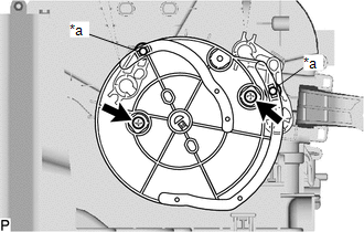
(b) Install the No. 1 blower damper servo sub-assembly with the 2 screws.
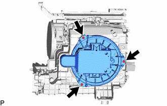
2. INSTALL BLOWER MOTOR WITH FAN SUB-ASSEMBLY
| (a) Install the blower motor with fan sub-assembly with the 3 screws. NOTICE: Replace the blower motor with fan sub-assembly if it has been dropped or subjected to a severe impact. |
|
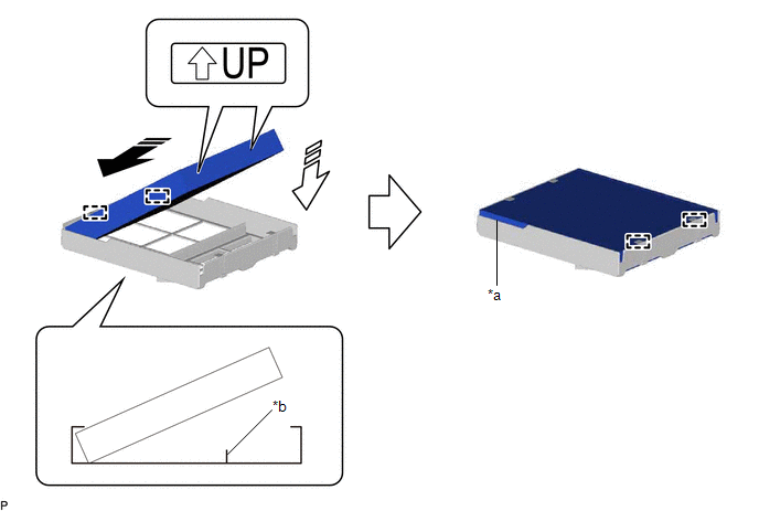
3. INSTALL CLEAN AIR FILTER
(a) Engage the 2 guides on the cutout side of the air filter case and then engage the 2 guides as shown in the illustration to install the clean air filter.
|
*a | Cutout |
*b | Rib |
 |
Install in this Direction (1) |
 |
Install in this Direction (2) |
NOTICE:
- Make sure that the "UP" marks are facing the correct direction before installing the clean air filter.
- Make sure that there is no clearance between the clean air filter and air filter case and that the clean air filter is not deformed.
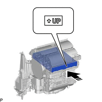
(b) Install the air filter sub-assembly as shown in the illustration.
|
|
Install in this Direction |
NOTICE:
Make sure that the "UP" mark is facing the correct direction before installing the air filter sub-assembly.
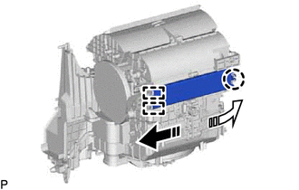
4. INSTALL AIR FILTER COVER PLATE
(a) Engage the 2 guides and claw as indicated by the arrows, in the order shown in the illustration to install the air filter cover plate.
|
|
Install in this Direction (1) |
|
|
Install in this Direction (2) |
READ NEXT:
 Installation
INSTALLATION PROCEDURE 1. INSTALL BLOWER ASSEMBLY
(a) Engage the 2 guides and 2 claws. (b) Install the blower assembly to the air conditioning radiator assembly with the 2 screws.
(c) Engage each gu
Components
COMPONENTS ILLUSTRATION
*A for Type A
*B for Type B
*1 COMPRESSOR ASSEMBLY WITH MAGNETIC CLUTCH
*2 NO. 1 COOLER REFRIGERANT DISCHARGE HOSE SUB-ASSEMBLY
*3 SUCT
SEE MORE:
System Description
SYSTEM DESCRIPTION PANORAMIC MOON ROOF SYSTEM DESCRIPTION
(a) The panoramic moon roof system controls the sliding roof operation using the sliding roof ECU (sliding roof drive gear assembly) and roof sunshade ECU (sliding roof drive gear assembly). Operating the panoramic moon roof switch (roof c
Reassembly
REASSEMBLY PROCEDURE 1. INSTALL FRONT BUMPER SIDE RETAINER LH
(a) Engage the 2 clips as shown in the illustration.
Install in this Direction
(b) Install the front bumper side retainer LH with the bolt.
Torque: 7.0 N
