Toyota Camry (XV70): Removal
REMOVAL
CAUTION / NOTICE / HINT
The necessary procedures (adjustment, calibration, initialization, or registration) that must be performed after parts are removed and installed, or replaced during rear upper control arm assembly removal/installation are shown below.
Necessary Procedures After Parts Removed/Installed/Replaced|
Replaced Part or Performed Procedure |
Necessary Procedure | Effect/Inoperative Function when Necessary Procedure not Performed |
Link |
|---|---|---|---|
| Rear wheel alignment adjustment |
|
|
|
|
Suspension, tires, etc. (The vehicle height changes because of suspension or tire replacement) |
Rear television camera assembly optical axis (Back camera position setting) |
Parking assist monitor system |
|
| Panoramic view monitor system |
| |
| Inspection After Repair |
|
|
CAUTION:
To prevent burns, do not touch the engine, exhaust pipe or other high temperature components while the engine is hot.
.png)
PROCEDURE
1. REMOVE REAR SUSPENSION MEMBER SUB-ASSEMBLY
for 2WD: Click here
.gif)
for AWD: Click here
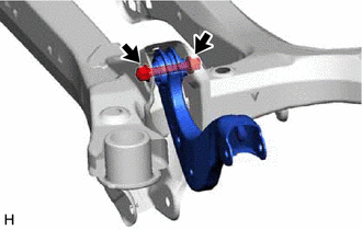
2. REMOVE REAR UPPER CONTROL ARM ASSEMBLY LH (for 2WD)
| (a) Remove the bolt, nut and rear upper control arm assembly LH from the rear suspension member sub-assembly. NOTICE: Because the nut has its own stopper, do not turn the nut. Loosen the bolt with the nut secured. |
|
3. REMOVE REAR UPPER CONTROL ARM ASSEMBLY RH (for 2WD)
HINT:
Perform the same procedure as for the LH side.
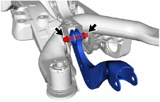
4. REMOVE REAR UPPER CONTROL ARM ASSEMBLY LH (for AWD)
| (a) Remove the bolt, nut and rear upper control arm assembly LH from the rear suspension member sub-assembly. NOTICE: Because the nut has its own stopper, do not turn the nut. Loosen the bolt with the nut secured. |
|
5. REMOVE REAR UPPER CONTROL ARM ASSEMBLY RH (for AWD)
HINT:
Perform the same procedure as for the LH side.
READ NEXT:
 Installation
INSTALLATION PROCEDURE 1. INSTALL REAR UPPER CONTROL ARM ASSEMBLY LH (for 2WD)
(a) Temporarily install the rear upper control arm assembly LH to the rear suspension member sub-assembly with the
Tire And Wheel
ComponentsCOMPONENTS ILLUSTRATION
*A for Steel Wheel
*B except Steel Wheel
*1 WHEEL ASSEMBLY
*2 AXLE HUB NUT
*3 WHEEL CAP
- -
Tig
SEE MORE:
Pressure Control Solenoid "H" Circuit Short to Battery (P281612)
DESCRIPTION Changing gears is performed by the ECM turning the solenoid (SL1, SL2, SL3, SL4, SL5 and SL6) valves on and off.
If an open or short occurs in any of the solenoid valve circuits, the ECM controls the remaining normal solenoid valves to allow the vehicle to be driven. If all of the sole
General Information
GENERAL INFORMATION
A large number of ECU controlled systems are used in this vehicle. In general, ECU controlled systems are considered to be very intricate, requiring a high level of technical knowledge to troubleshoot. However, most problem checking procedures only involve inspecting the ECU
