
Toyota Camry (XV70): Removal
REMOVAL
CAUTION / NOTICE / HINT
The necessary procedures (adjustment, calibration, initialization or registration) that must be performed after parts are removed and installed, or replaced during combination meter assembly removal/installation are shown below.
Necessary Procedures After Parts Removed/Installed/Replaced|
Replaced Part or Performed Procedure |
Necessary Procedure | Effect/Inoperative Function when Necessary Procedure not Performed |
Link |
|---|---|---|---|
|
Disconnect cable from negative battery terminal |
Perform steering sensor zero point calibration |
Lane Tracing Assist System |
|
|
Pre-collision system | |||
|
Memorize steering angle neutral point |
Parking assist monitor system |
| |
|
Panoramic view monitor system |
|
PROCEDURE
1. PRECAUTION
NOTICE:
After turning the ignition switch off, waiting time may be required before disconnecting the cable from the negative (-) battery terminal. Therefore, make sure to read the disconnecting the cable from the negative (-) battery terminal notices before proceeding with work.
Click here 
2. DISCONNECT CABLE FROM NEGATIVE BATTERY TERMINAL
for A25A-FKS:
Click here
for 2GR-FKS:
Click here
NOTICE:
When disconnecting the cable, some systems need to be initialized after the cable is reconnected.
Click here
3. REMOVE NO. 1 METER HOOD CLUSTER
Click here
4. REMOVE NO. 2 METER HOOD CLUSTER
Click here
5. REMOVE INSTRUMENT CLUSTER FINISH PANEL ASSEMBLY
(a) Operate the tilt and telescopic lever to fully extend and lower the steering column assembly.
(b) Apply protective tape to the area shown in the illustration.
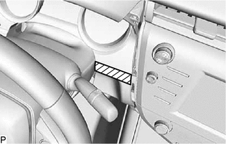
 |
Protective Tape |
(c) Apply protective tape to the area shown in the illustration.
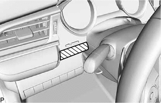
|
|
Protective Tape |
(d) Disengage the 2 claws and 4 clips to separate the instrument cluster finish panel assembly.
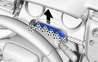
 |
Remove in this Direction |
| (e) Remove the 2 clips. |
|
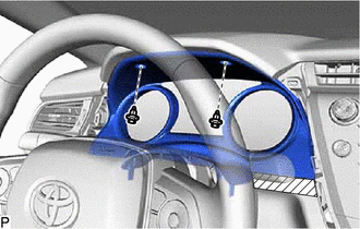
(f) Disengage the 2 clips as shown in the illustration.
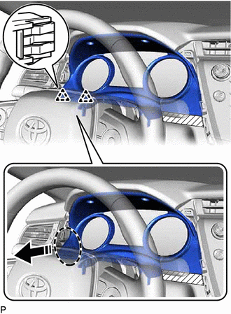
 |
Place Hand Here |
|
|
Remove in this Direction |
(g) Disengage the 2 clips as shown in the illustration.
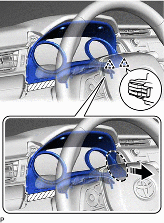
|
|
Place Hand Here |
|
|
Remove in this Direction |
(h) Disengage the 2 guides as shown in the illustration.
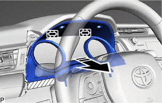
|
|
Remove in this Direction |
(i) Disconnect the connector to remove the instrument cluster finish panel assembly.
6. REMOVE COMBINATION METER ASSEMBLY
| (a) Remove the 3 screws. |
|
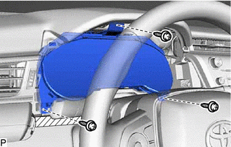
(b) Disengage the 2 clips as shown in the illustration.
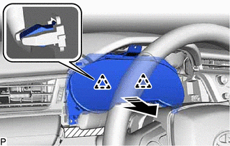
|
|
Remove in this Direction |
(c) Disengage the clamp.
(d) Disconnect each connector to remove the combination meter assembly.
READ NEXT:
SEE MORE:
 Parts Location
PARTS LOCATION ILLUSTRATION
*1 FORWARD RECOGNITION CAMERA
*2 MILLIMETER WAVE RADAR SENSOR ASSEMBLY
*3 ECM
*4 SKID CONTROL ECU (BRAKE ACTUATOR ASSEMBLY) ILLUSTRATION
*1 STEERING PAD SWITCH ASSEMBLY
*2 COMBINATION METER ASSEMBLY
*3
Air outlets - Automatic air conditioning system (without "SYNC" button)
■ Location of air outlets
The air outlets and air volume
change according to the
selected airflow mode.
■ Adjusting the position of and opening and closing the air outlets
Direct air flow to the left or
right, up or down.
Turn the knob to open or
close the vent.
■Using aut
