Toyota Camry (XV70): Parts Location
PARTS LOCATION
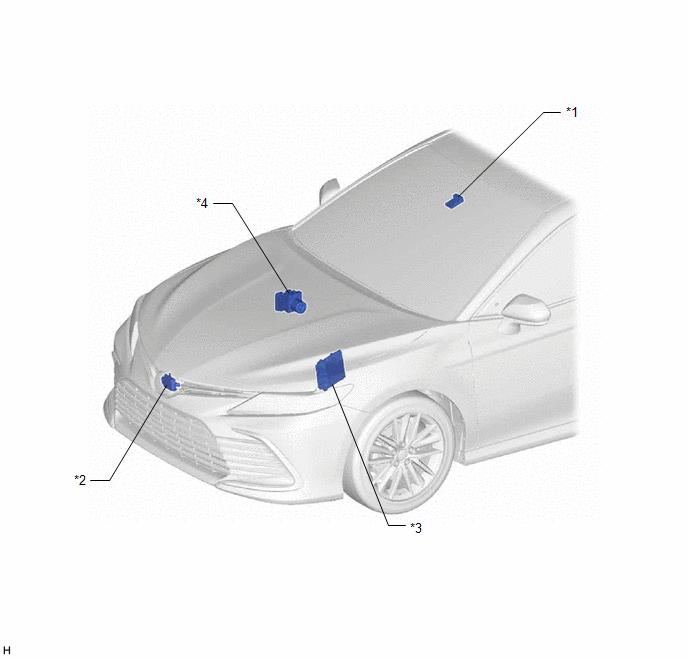
ILLUSTRATION
|
*1 | FORWARD RECOGNITION CAMERA |
*2 | MILLIMETER WAVE RADAR SENSOR ASSEMBLY |
|
*3 | ECM |
*4 | SKID CONTROL ECU (BRAKE ACTUATOR ASSEMBLY) |
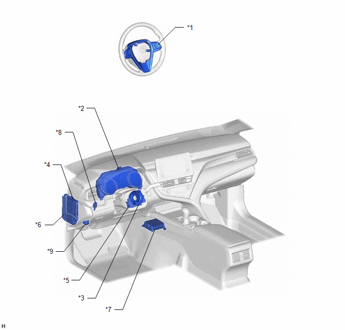
ILLUSTRATION
|
*1 | STEERING PAD SWITCH ASSEMBLY |
*2 | COMBINATION METER ASSEMBLY |
|
*3 | SPIRAL CABLE SUB-ASSEMBLY |
*4 | MAIN BODY ECU (MULTIPLEX NETWORK BODY ECU) |
|
*5 | STEERING SENSOR |
*6 | INSTRUMENT PANEL JUNCTION BLOCK ASSEMBLY - ECU-IG1 NO. 3 FUSE - ECU-IG2 NO. 3 FUSE - STOP FUSE |
|
*7 | AIRBAG SENSOR ASSEMBLY |
*8 | STOP LIGHT SWITCH ASSEMBLY |
|
*9 | DLC3 |
- | - |
READ NEXT:
 System Diagram
SYSTEM DIAGRAM
How To Proceed With Troubleshooting
CAUTION / NOTICE / HINT
HINT:
Before performing troubleshooting for the dynamic radar cruise control system, perform troubleshooting for the pre-collision system.
Click here
*: Use the Tec
Road Test
ROAD TEST
HINT:
The dynamic radar cruise control system has 2 cruise control modes: constant speed control mode and vehicle-to-vehicle distance control mode.
Vehicle-to-vehicle distance con
SEE MORE:
Removal
REMOVAL CAUTION / NOTICE / HINT
The necessary procedures (adjustment, calibration, initialization, or registration) that must be performed after parts are replaced during forward recognition camera removal/installation are shown below. Necessary Procedure After Parts Removed/Installed/Replaced
Start Up Signal Circuit between Radio Receiver Assembly and Navigation ECU
DESCRIPTION This circuit includes the navigation ECU and radio and display receiver assembly. WIRING DIAGRAM
PROCEDURE
1.
CHECK HARNESS AND CONNECTOR (RADIO AND DISPLAY RECEIVER ASSEMBLY - NAVIGATION ECU)
(a) Disconnect the K1 radio and display receiver assembly connector. (b) Dis
© 2023-2026 Copyright www.tocamry.com
