Toyota Camry (XV70): Components
COMPONENTS
ILLUSTRATION
.png)
|
*A | for 2WD |
*B | for RH Side |
|
*C | for LH Side |
- | - |
|
*1 | NO. 1 FLOOR UNDER COVER |
*2 | NO. 2 FLOOR UNDER COVER |
.png) |
N*m (kgf*cm, ft.*lbf): Specified torque |
- | - |
ILLUSTRATION
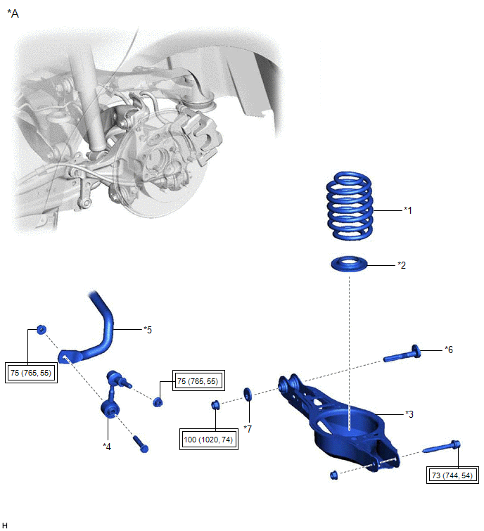
|
*A | for 2WD |
- | - |
|
*1 | REAR COIL SPRING |
*2 | REAR LOWER COIL SPRING INSULATOR |
|
*3 | REAR NO. 2 SUSPENSION ARM ASSEMBLY |
*4 | REAR STABILIZER LINK ASSEMBLY |
|
*5 | REAR STABILIZER BAR |
*6 | REAR SUSPENSION TOE ADJUST CAM SUB-ASSEMBLY |
|
*7 | NO. 2 CAMBER ADJUST CAM |
- | - |
.png) |
Tightening torque for "Major areas involving basic vehicle performance such as moving/turning/stopping": N*m (kgf*cm, ft.*lbf) |
- | - |
ILLUSTRATION
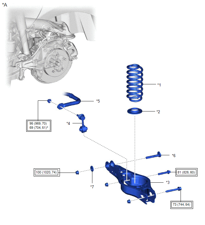
|
*A | for AWD |
- | - |
|
*1 | REAR COIL SPRING |
*2 | REAR LOWER COIL SPRING INSULATOR |
|
*3 | REAR NO. 2 SUSPENSION ARM ASSEMBLY |
*4 | REAR STABILIZER LINK ASSEMBLY |
|
*5 | REAR STABILIZER BAR |
*6 | REAR SUSPENSION TOE ADJUST CAM SUB-ASSEMBLY |
|
*7 | NO. 2 CAMBER ADJUST CAM |
- | - |
|
|
Tightening torque for "Major areas involving basic vehicle performance such as moving/turning/stopping": N*m (kgf*cm, ft.*lbf) |
- | - |
ILLUSTRATION
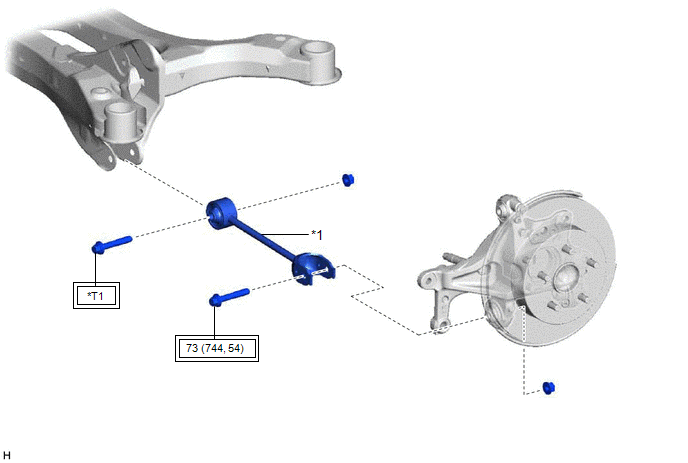
|
*1 | REAR NO. 1 SUSPENSION ARM ASSEMBLY |
- | - |
|
|
Tightening torque for "Major areas involving basic vehicle performance such as moving/turning/stopping": N*m (kgf*cm, ft.*lbf) |
*T1 | for 2WD: 73 N*m (744 kgf*cm, 54 ft.*lbf) for AWD: 115 N*m (1173 kgf*cm, 85 ft.*lbf) |
READ NEXT:
 Removal
REMOVAL CAUTION / NOTICE / HINT
The necessary procedures (adjustment, calibration, initialization, or registration) that must be performed after parts are removed and installed, or replaced during r
Installation
INSTALLATION CAUTION / NOTICE / HINT
HINT:
Use the same procedure for the RH side and LH side.
The following procedure is for the LH side.
PROCEDURE 1. TEMPORARILY INSTALL REAR NO. 1 SUS
SEE MORE:
Components
COMPONENTS ILLUSTRATION
*1 V-BANK COVER SUB-ASSEMBLY
*2 AIR FUEL RATIO SENSOR (for Bank 1)
*3 AIR FUEL RATIO SENSOR (for Bank 2)
- -
N*m (kgf*cm, ft.*lbf): Specified torque
* For use with SST
Basic Inspection
CAUTION / NOTICE / HINT When a malfunction is not confirmed by the DTC check, troubleshooting should be carried out for all circuits considered to be possible causes of the problem. In many cases, by carrying out the basic engine check shown in the following procedure, the location of the problem ca
