Toyota Camry (XV70): Removal
REMOVAL
CAUTION / NOTICE / HINT
The necessary procedures (adjustment, calibration, initialization, or registration) that must be performed after parts are removed and installed, or replaced during rear suspension arm assembly removal/installation are shown below.
Necessary Procedures After Parts Removed/Installed/Replaced|
Replaced Part or Performed Procedure |
Necessary Procedure | Effect/Inoperative Function when Necessary Procedure not Performed |
Link |
|---|---|---|---|
| Rear wheel alignment adjustment |
|
|
|
|
Suspension, tires, etc. (The vehicle height changes because of suspension or tire replacement) |
Rear television camera assembly optical axis (Back camera position setting) |
Parking assist monitor system |
|
| Panoramic view monitor system |
|
HINT:
- Use the same procedure for the RH side and LH side.
- The following procedure is for the LH side.
PROCEDURE
1. REMOVE REAR WHEEL
Click here
.gif)
2. REMOVE NO. 2 FLOOR UNDER COVER (for 2WD)
(a) for LH Side:
Click here
3. REMOVE NO. 1 FLOOR UNDER COVER (for 2WD)
(a) for RH Side:
Click here
4. REMOVE REAR STABILIZER LINK ASSEMBLY
for 2WD: Click here
for AWD: Click here
5. REMOVE REAR COIL SPRING
Click here
6. REMOVE REAR LOWER COIL SPRING INSULATOR
Click here
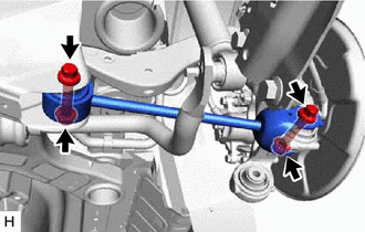
7. REMOVE REAR NO. 2 SUSPENSION ARM ASSEMBLY
| (a) Remove the nut, No. 2 camber adjust cam, rear suspension toe adjust cam sub-assembly and rear No. 2 suspension arm assembly. NOTICE: Hold the rear suspension toe adjust cam sub-assembly while rotating the nut. |
|
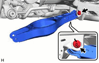
8. REMOVE REAR NO. 1 SUSPENSION ARM ASSEMBLY
| (a) Remove the 2 bolts, 2 nuts and rear No. 1 suspension arm assembly from the rear axle carrier sub-assembly and rear suspension member sub-assembly. NOTICE: Because the nut has its own stopper, do not turn the nut. Loosen the bolt with the nut secured. |
|
READ NEXT:
 Installation
INSTALLATION CAUTION / NOTICE / HINT
HINT:
Use the same procedure for the RH side and LH side.
The following procedure is for the LH side.
PROCEDURE 1. TEMPORARILY INSTALL REAR NO. 1 SUS
Components
COMPONENTS ILLUSTRATION
*A for 2WD
*B for RH Side
*C for LH Side
- -
*1 NO. 1 FLOOR UNDER COVER
*2 NO. 2 FLOOR UNDER COVER
N*m (k
SEE MORE:
Installation
INSTALLATION PROCEDURE 1. INSTALL NO. 5 ANTENNA CORD SUB-ASSEMBLY (w/ Manual (SOS) Switch)
(a) Engage the 5 clamps to install the No. 5 antenna cord sub-assembly.
(b) Connect the connector. 2. INSTALL NO. 2 ANTENNA CORD SUB-ASSEMBLY
HINT: Butyl tape and adhesive tape are not available as suppl
Components
COMPONENTS ILLUSTRATION
*1 NO. 1 FLOOR UNDER COVER
*2 NO. 2 FLOOR UNDER COVER
N*m (kgf*cm, ft.*lbf): Specified torque
- - ILLUSTRATION
*A w/ Fuel Outlet Valve Assembly
*B w/o Fuel Outlet Valve Assembly
*1 FUEL TANK ASSEMBLY
