Toyota Camry (XV70): Components
Toyota Camry Repair Manual XV70 (2018-2024) / Engine, Hybrid System / 2gr-fks (fuel) / Fuel Tank / Components
COMPONENTS
ILLUSTRATION
|
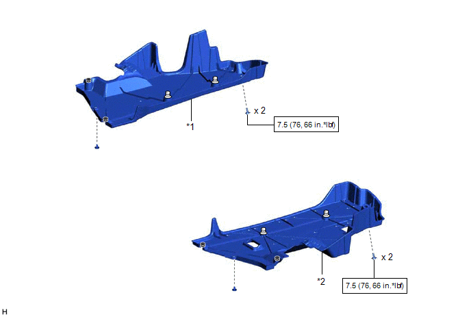
*1 | NO. 1 FLOOR UNDER COVER |
*2 | NO. 2 FLOOR UNDER COVER |
.png) |
N*m (kgf*cm, ft.*lbf): Specified torque |
- | - |
ILLUSTRATION
|
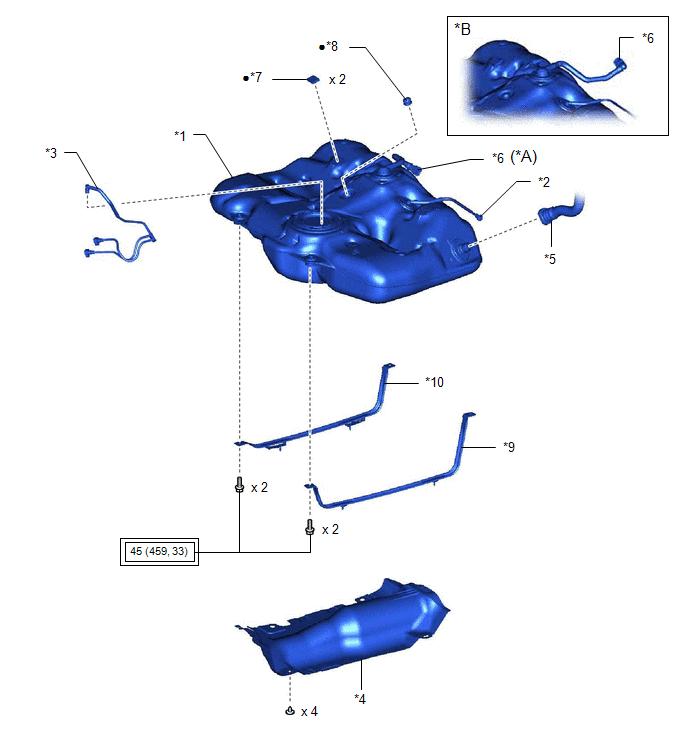
*A | w/ Fuel Outlet Valve Assembly |
*B | w/o Fuel Outlet Valve Assembly |
|
*1 | FUEL TANK ASSEMBLY |
*2 | FUEL TANK BREATHER TUBE SUB-ASSEMBLY |
|
*3 | FUEL TANK MAIN TUBE SUB-ASSEMBLY |
*4 | NO. 1 FUEL TANK PROTECTOR |
|
*5 | FUEL TANK TO FILLER PIPE HOSE |
*6 | FUEL CUT OFF VALVE WITH TUBE ASSEMBLY |
|
*7 | NO. 1 FUEL TANK CUSHION |
*8 | NO. 6 FUEL TANK CUSHION |
|
*9 | NO. 1 FUEL TANK BAND SUB-ASSEMBLY LH |
*10 | NO. 1 FUEL TANK BAND SUB-ASSEMBLY RH |
.png) |
Tightening torque for "Major areas involving basic vehicle performance such as moving/turning/stopping": N*m (kgf*cm, ft.*lbf) |
● | Non-reusable part |
READ NEXT:
 Removal
REMOVAL CAUTION / NOTICE / HINT
The necessary procedures (adjustment, calibration, initialization or registration) that must be performed after parts are removed and installed, or replaced during fu
Installation
INSTALLATION PROCEDURE 1. INSTALL NO. 1 FUEL TANK CUSHION
(a) Install 2 new No. 1 fuel tank cushions to the fuel tank assembly. 2. INSTALL NO. 6 FUEL TANK CUSHION
(a) Install a new No. 6 fuel tank
Components
COMPONENTS ILLUSTRATION
*1 NO. 1 FLOOR UNDER COVER
*2 NO. 2 FLOOR UNDER COVER
N*m (kgf*cm, ft.*lbf): Specified torque
- - ILLUSTRATION
*A w/
SEE MORE:
Diagnostic Trouble Code Chart
DIAGNOSTIC TROUBLE CODE CHART Dynamic Torque Control AWD System
DTC No. Detection Item
Link C120C
Linear Solenoid Power Supply System Malfunction
C1241 Low or High Power Supply Voltage
C1280 Engine Circuit Malfunction
C129
Driving assist systems
To keep driving safety and performance, the following systems
operate automatically in response to various driving situations.
Be aware, however, that these systems are supplementary and
should not be relied upon too heavily when operating the vehicle.
◆ ABS (Anti-lock Brake System)
Helps t
© 2023-2026 Copyright www.tocamry.com
