Toyota Camry (XV70): Removal
REMOVAL
CAUTION / NOTICE / HINT
The necessary procedures (adjustment, calibration, initialization or registration) that must be performed after parts are removed and installed, or replaced during fuel tank assembly removal/installation are shown below.
Necessary Procedures After Parts Removed/Installed/Replaced|
Replaced Part or Performed Procedure |
Necessary Procedure | Effect/Inoperative Function when Necessary Procedure not Performed |
Link |
|---|---|---|---|
|
Battery terminal is disconnected/reconnected |
Perform steering sensor zero point calibration |
Lane Tracing Assist System |
|
|
Pre-collision System | |||
|
Memorize steering angle neutral point |
Parking Assist Monitor System |
| |
|
Panoramic View Monitor System |
| ||
|
Gas leak from exhaust system is repaired |
Inspection after repair |
|
|
CAUTION:
- Never perform work on fuel system components near any possible ignition sources.
.png)
- Vaporized fuel could ignite, resulting in a serious accident.
- Do not perform work on fuel system components without first disconnecting the cable from the negative (-) battery terminal.
.png)
- Sparks could cause vaporized fuel to ignite, resulting in a serious accident.
- The fuel tank assembly is very heavy. Be sure to follow the procedure described in the repair manual, or the fuel tank assembly may fall off the engine lifter.
.png)
PROCEDURE
1. REMOVE FUEL SUCTION TUBE WITH PUMP AND GAUGE ASSEMBLY
Click here .gif)
2. DRAIN FUEL
3. REMOVE CENTER EXHAUST PIPE ASSEMBLY
Click here
4. REMOVE NO. 2 FLOOR UNDER COVER
Click here
5. REMOVE NO. 1 FLOOR UNDER COVER
Click here
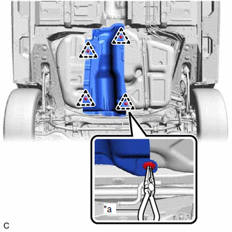
6. REMOVE NO. 1 FUEL TANK PROTECTOR
| (a) Using needle nose pliers, remove the 4 clips and No. 1 fuel tank protector from the fuel tank assembly. |
|
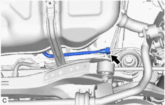
7. DISCONNECT FUEL TANK MAIN TUBE SUB-ASSEMBLY
| (a) Disconnect the fuel tank main tube sub-assembly from the fuel pipe. Click here |
|
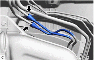
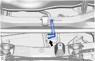
8. DISCONNECT FUEL TANK BREATHER TUBE SUB-ASSEMBLY
| (a) Disconnect the fuel tank breather tube sub-assembly from the fuel pipe. Click here |
|
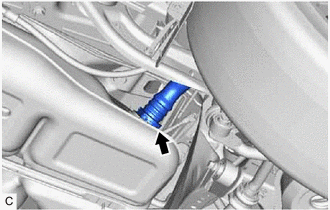
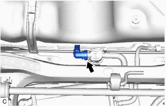
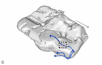
9. DISCONNECT FUEL TANK TO FILLER PIPE HOSE
| (a) Disconnect the fuel tank to filler pipe hose from the fuel tank assembly. Click here |
|
10. REMOVE FUEL TANK ASSEMBLY
CAUTION:
The fuel tank assembly is very heavy. Be sure to follow the procedure described in the repair manual, or the fuel tank assembly may fall off the engine lifter.
(a) w/ Fuel Outlet Valve Assembly:
| (1) Disconnect the fuel cut off valve with tube assembly from the fuel outlet valve assembly. Click here |
|
(b) w/o Fuel Outlet Valve Assembly:
| (1) Disconnect the fuel cut off valve with tube assembly from the canister (charcoal canister assembly). Click here |
|
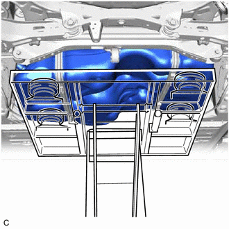
| (c) Support the fuel tank assembly using an engine lifter. HINT: Using height adjustment attachments and plate lift attachments, keep the fuel tank assembly horizontal. |
|
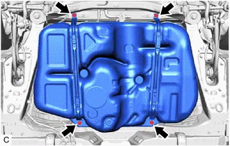
| (d) Remove the 4 bolts, No. 1 fuel tank band sub-assembly LH and No. 1 fuel tank band sub-assembly RH. |
|
(e) Lower the engine lifter to remove the fuel tank assembly.
NOTICE:
- Be careful not to drop the fuel tank assembly.
- When removing the fuel tank assembly, tilt it slightly to prevent it from interfering with the surrounding parts.
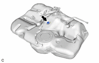
11. REMOVE FUEL TANK MAIN TUBE SUB-ASSEMBLY
| (a) Disengage the clamp to remove the fuel tank main tube sub-assembly from the fuel tank assembly. |
|
12. REMOVE NO. 6 FUEL TANK CUSHION
| (a) Remove the No. 6 fuel tank cushion from the fuel tank assembly. |
|
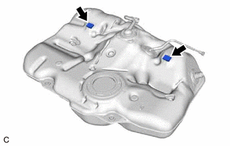
13. REMOVE NO. 1 FUEL TANK CUSHION
| (a) Remove the 2 No. 1 fuel tank cushions from the fuel tank assembly. |
|
READ NEXT:
 Installation
INSTALLATION PROCEDURE 1. INSTALL NO. 1 FUEL TANK CUSHION
(a) Install 2 new No. 1 fuel tank cushions to the fuel tank assembly. 2. INSTALL NO. 6 FUEL TANK CUSHION
(a) Install a new No. 6 fuel tank
Components
COMPONENTS ILLUSTRATION
*1 NO. 1 FLOOR UNDER COVER
*2 NO. 2 FLOOR UNDER COVER
N*m (kgf*cm, ft.*lbf): Specified torque
- - ILLUSTRATION
*A w/
Removal
REMOVAL CAUTION / NOTICE / HINT
The necessary procedures (adjustment, calibration, initialization or registration) that must be performed after parts are removed and installed, or replaced during fu
SEE MORE:
Radio Receiver Assembly Communication Stop Mode
DESCRIPTION
Detection Item Symptom
Trouble Area Radio Receiver Assembly Communication Stop Mode
Any of the following conditions are met:
Communication stop for "Display and Navigation (AVN)" is indicated on the "Communication Bus Check" screen of the Techstream.
C
Precaution
PRECAUTION PRECAUTION FOR DISCONNECTING CABLE FROM NEGATIVE BATTERY TERMINAL
NOTICE: When disconnecting the cable from the negative (-) battery terminal, initialize the following systems after the cable is reconnected.
System Name See Procedure
Lane Tracing Assist System
