Toyota Camry (XV70): Installation
INSTALLATION
PROCEDURE
1. INSTALL NO. 1 FUEL TANK CUSHION
(a) Install 2 new No. 1 fuel tank cushions to the fuel tank assembly.
2. INSTALL NO. 6 FUEL TANK CUSHION
(a) Install a new No. 6 fuel tank cushion to the fuel tank assembly.
3. INSTALL FUEL TANK MAIN TUBE SUB-ASSEMBLY
(a) Engage the clamp to install the fuel tank main tube sub-assembly to the fuel tank assembly.
4. INSTALL FUEL TANK ASSEMBLY
CAUTION:
The fuel tank assembly is very heavy. Be sure to follow the procedure described in the repair manual, or the fuel tank assembly may fall off the engine lifter.
.png)
(a) Set the fuel tank assembly on an engine lifter.
NOTICE:
Using height adjustment attachments and plate lift attachments, keep the fuel tank assembly horizontal.
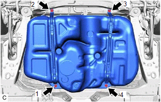
| (b) Using the engine lifter, slowly raise the fuel tank assembly, and then install the fuel tank assembly, No. 1 fuel tank band sub-assembly LH and No. 1 fuel tank band sub-assembly RH with the 4 bolts in the order shown in the illustration. Torque: 45 N·m {459 kgf·cm, 33 ft·lbf} NOTICE:
|
|
(c) w/ Fuel Outlet Valve Assembly:
(1) Connect the fuel cut off valve with tube assembly to the fuel outlet valve assembly.
Click here .gif)
(d) w/o Fuel Outlet Valve Assembly:
(1) Connect the fuel cut off valve with tube assembly to the canister (charcoal canister assembly).
Click here
5. CONNECT FUEL TANK TO FILLER PIPE HOSE
(a) Connect the fuel tank to filler pipe hose to the fuel tank assembly.
Click here
6. CONNECT FUEL TANK BREATHER TUBE SUB-ASSEMBLY
(a) Connect the fuel tank breather tube sub-assembly to the fuel pipe.
Click here
7. CONNECT FUEL TANK MAIN TUBE SUB-ASSEMBLY
(a) Connect the fuel tank main tube sub-assembly to the fuel pipe.
Click here
8. INSTALL NO. 1 FUEL TANK PROTECTOR
(a) Install the No. 1 fuel tank protector to the fuel tank assembly with the 4 clips.
9. INSTALL NO. 1 FLOOR UNDER COVER
Click here
10. INSTALL NO. 2 FLOOR UNDER COVER
Click here
11. INSTALL CENTER EXHAUST PIPE ASSEMBLY
Click here
12. INSTALL FUEL SUCTION TUBE WITH PUMP AND GAUGE ASSEMBLY
Click here
13. ADD FUEL
READ NEXT:
 Components
COMPONENTS ILLUSTRATION
*1 NO. 1 FLOOR UNDER COVER
*2 NO. 2 FLOOR UNDER COVER
N*m (kgf*cm, ft.*lbf): Specified torque
- - ILLUSTRATION
*A w/
Removal
REMOVAL CAUTION / NOTICE / HINT
The necessary procedures (adjustment, calibration, initialization or registration) that must be performed after parts are removed and installed, or replaced during fu
Installation
INSTALLATION PROCEDURE 1. INSTALL NO. 1 FUEL TANK CUSHION
(a) Install 2 new No. 1 fuel tank cushions to the fuel tank assembly. 2. INSTALL NO. 6 FUEL TANK CUSHION
(a) Install a new No. 6 fuel tank
SEE MORE:
Precaution
PRECAUTION PRECAUTION FOR DISCONNECTING CABLE FROM NEGATIVE BATTERY TERMINAL
NOTICE: When disconnecting the cable from the negative (-) battery terminal, initialize the following systems after the cable is reconnected.
System Name See Procedure
Lane Tracing Assist System
Inspection
INSPECTION PROCEDURE 1. INSPECT REAR COMBINATION LIGHT LED (for Bulb Type Back-up Light)
*a Component without harness connected
(Rear Combination Light LED) (a) Apply battery voltage to the rear combination light LED and check that the lights illuminate.
OK:
Conditi
