
Toyota Camry (XV70): Inspection
INSPECTION
PROCEDURE
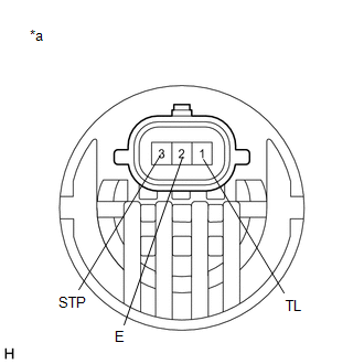
1. INSPECT REAR COMBINATION LIGHT LED (for Bulb Type Back-up Light)
|
*a | Component without harness connected (Rear Combination Light LED) |
(a) Apply battery voltage to the rear combination light LED and check that the lights illuminate.
OK:
|
Condition | Specified Condition |
|---|---|
|
Battery positive (+) → Terminal 1 (TL) Battery negative (-) → Terminal 2 (E) |
Taillight illuminates |
|
Battery positive (+) → Terminal 3 (STP) Battery negative (-) → Terminal 2 (E) |
Stop light illuminates |
If the result is not as specified, replace the rear combination light LED.
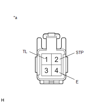
2. INSPECT REAR COMBINATION LIGHT ASSEMBLY LH (for TMMK Made Bulb Type Back-up Light)
|
*a | Component without harness connected (Rear Combination Light Assembly LH) |
(a) Apply battery voltage to the rear combination light assembly LH and check that the lights illuminate.
OK:
|
Condition | Specified Condition |
|---|---|
|
Battery positive (+) → Terminal 1 (TL) Battery negative (-) → Terminal 4 (E) |
Taillight illuminates |
|
Battery positive (+) → Terminal 2 (STP) Battery negative (-) → Terminal 4 (E) |
Stop light illuminates |
If the result is not as specified, replace the rear combination light assembly LH.
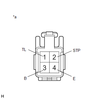
3. INSPECT REAR COMBINATION LIGHT ASSEMBLY LH (for TMMK Made LED Type Back-up Light)
|
*a | Component without harness connected (Rear Combination Light Assembly LH) |
(a) Apply battery voltage to the rear combination light assembly LH and check that the lights illuminate.
OK:
|
Condition | Specified Condition |
|---|---|
|
Battery positive (+) → Terminal 1 (TL) Battery negative (-) → Terminal 4 (E) |
Taillight and side marker light illuminate |
|
Battery positive (+) → Terminal 2 (STP) Battery negative (-) → Terminal 4 (E) |
Stop light illuminates |
|
Battery positive (+) → Terminal 3 (B) Battery negative (-) → Terminal 4 (E) |
Turn signal light illuminates |
If the result is not as specified, replace the rear combination light assembly LH.
4. INSPECT REAR COMBINATION LIGHT ASSEMBLY RH (for TMMK Made Bulb Type Back-up Light)
|
*a | Component without harness connected (Rear Combination Light Assembly RH) |
(a) Apply battery voltage to the rear combination light assembly RH and check that the lights illuminate.
OK:
|
Condition | Specified Condition |
|---|---|
|
Battery positive (+) → Terminal 1 (TL) Battery negative (-) → Terminal 4 (E) |
Taillight illuminates |
|
Battery positive (+) → Terminal 2 (STP) Battery negative (-) → Terminal 4 (E) |
Stop light illuminates |
If the result is not as specified, replace the rear combination light assembly RH.
5. INSPECT REAR COMBINATION LIGHT ASSEMBLY RH (for TMMK Made LED Type Back-up Light)
|
*a | Component without harness connected (Rear Combination Light Assembly RH) |
(a) Apply battery voltage to the rear combination light assembly RH and check that the lights illuminate.
OK:
|
Condition | Specified Condition |
|---|---|
|
Battery positive (+) → Terminal 1 (TL) Battery negative (-) → Terminal 4 (E) |
Taillight and side marker light illuminate |
|
Battery positive (+) → Terminal 2 (STP) Battery negative (-) → Terminal 4 (E) |
Stop light illuminates |
|
Battery positive (+) → Terminal 3 (B) Battery negative (-) → Terminal 4 (E) |
Turn signal light illuminates |
If the result is not as specified, replace the rear combination light assembly RH.
READ NEXT:
 Reassembly
REASSEMBLY CAUTION / NOTICE / HINT
HINT:
Use the same procedure for the RH side and LH side.
The following procedure is for the LH side.
PROCEDURE 1. INSTALL REAR COMBINATION LIGHT
Installation
INSTALLATION CAUTION / NOTICE / HINT
HINT:
Use the same procedure for the RH side and LH side.
The following procedure is for the LH side.
PROCEDURE 1. INSTALL REAR COMBINATION LIGH
SEE MORE:
System Diagram
SYSTEM DIAGRAM
Communication Table
Sender Receiver
Signal Line
Main Body ECU (Multiplex Network Body ECU)
Sliding Roof ECU (Sliding Roof Drive Gear Assembly)
Sliding roof operation permission signal
IG signal
Front door courtesy lig
Torque Converter Clutch Pressure Control Solenoid Control Actuator Stuck Off (P27567F)
DESCRIPTION The ECM controls the solenoid (SLU) valve using a predetermined current, and performs lock-up and flex lock-up control.
The ECM compares the engagement condition of the lock-up clutch with the lock-up schedule in the ECM memory to detect mechanical malfunctions of the solenoid (SLU) va
