
Toyota Camry (XV70): Installation
INSTALLATION
CAUTION / NOTICE / HINT
HINT:
- Use the same procedure for the RH side and LH side.
- The following procedure is for the LH side.
PROCEDURE
1. INSTALL REAR COMBINATION LIGHT ASSEMBLY
(a) Engage the grommet.
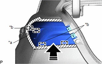
(b) Engage the 3 guides and pin to temporarily install the rear combination light assembly as shown in the illustration.
|
*a | Pin |
|
*b | Guide |
.png) |
Install in this Direction |
(c) Install the rear combination light assembly with the 2 screws.
(d) Remove the protective tape.
(e) Connect the connector.
2. INSTALL REAR COMBINATION LIGHT COVER
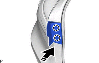
(a) Engage the 2 claws as shown in the illustration.
|
|
Install in this Direction |
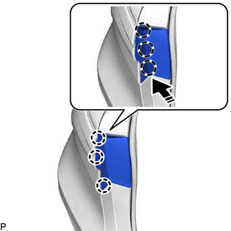
(b) Push the areas shown in the illustration in the direction indicated by the arrow to engage the 3 claws and install the rear combination light cover.
.png) |
Area to Push |
|
|
Push in this Direction |
3. INSTALL LUGGAGE COMPARTMENT TRIM INNER COVER LH (for LH Side)
Click here .gif)
4. INSTALL LUGGAGE COMPARTMENT TRIM INNER COVER RH (for RH Side)
Click here
5. INSTALL REAR FLOOR FINISH PLATE
Click here
6. INSTALL LUGGAGE COMPARTMENT DOOR STRIKER COVER
Click here
7. INSTALL NO. 1 LUGGAGE COMPARTMENT TRIM HOOK
Click here
8. INSTALL SPARE WHEEL COVER TRAY
Click here
9. INSTALL SPARE WHEEL COVER ASSEMBLY
Click here
READ NEXT:
 Components
COMPONENTS ILLUSTRATION
*1 LUGGAGE COMPARTMENT DOOR COVER
- - ILLUSTRATION
*A for LED Type Back-up Light
*B for Bulb Type Back-up Light
*1
Removal
REMOVAL CAUTION / NOTICE / HINT
HINT:
Use the same procedure for the RH side and LH side.
The following procedure is for the LH side.
PROCEDURE 1. REMOVE LUGGAGE COMPARTMENT DOOR CO
SEE MORE:
Throttle / Pedal Position Sensor / Switch "A" Circuit Voltage Out of Range (P01201C)
DESCRIPTION Refer to DTC P012011. Click here
DTC No. Detection Item
DTC Detection Condition Trouble Area
MIL Memory
Note P01201C
Throttle / Pedal Position Sensor / Switch "A" Circuit Voltage Out of Range
The difference between the output voltage of VTA1
Right Front Wheel Speed Sensor Circuit Intermittent (C05061F)
DESCRIPTION Refer to DTC C050612 Click here
DTC No. Detection Item
DTC Detection Condition Trouble Area
C05061F Right Front Wheel Speed Sensor Circuit Intermittent
The speed sensor signal is excessively noisy.
The calculated change in wheel speed is more
