Toyota Camry (XV70): System Diagram
SYSTEM DIAGRAM
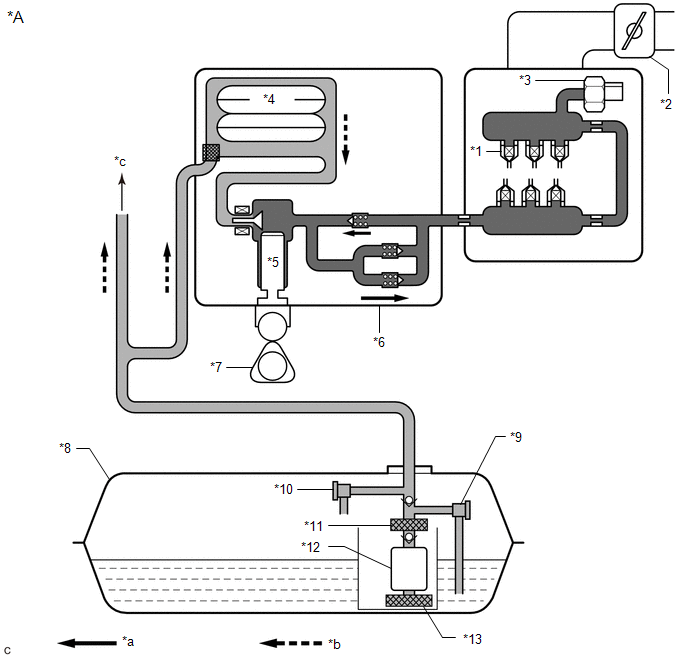
FUEL FLOW DIAGRAM
|
*A | for Direct Injection |
- | - |
|
*1 | Fuel Injector Assembly |
*2 | Throttle Body with Motor Assembly |
|
*3 | Fuel Pressure Sensor (Fuel Delivery Pipe with Sensor Assembly LH) (for High Pressure) |
*4 | Fuel Pressure Pulsation Damper Assembly |
|
*5 | Plunger |
*6 | Fuel Pump Assembly (for High Pressure) |
|
*7 | Camshaft |
*8 | Fuel Tank Assembly |
|
*9 | Fuel Main Valve Assembly (for Low Pressure) |
*10 | Fuel Main Valve Assembly (for High Pressure) |
|
*11 | Fuel Filter |
*12 | Fuel Pump (for Low Pressure) |
|
*13 | Suction Filter |
- | - |
|
*a | High Pressure Fuel Line |
*b | Low Pressure Fuel Line |
|
*c | to Fuel Injector Assembly (for Port Injection) |
- | - |

|
*A | for Port Injection |
- | - |
|
*1 | Throttle Body with Motor Assembly |
*2 | Fuel Injector Assembly |
|
*3 | Fuel Tank Assembly |
*4 | Fuel Pressure Sensor (Fuel Delivery Pipe with Sensor Assembly) (for Low Pressure) |
|
*5 | Fuel Main Valve Assembly (for Low Pressure) |
*6 | Fuel Main Valve Assembly (for High Pressure) |
|
*7 | Fuel Filter |
*8 | Fuel Pump (for Low Pressure) |
|
*9 | Suction Filter |
- | - |
|
*a | Low Pressure Fuel Line |
*b | to Fuel Pump Assembly (for High Pressure) |
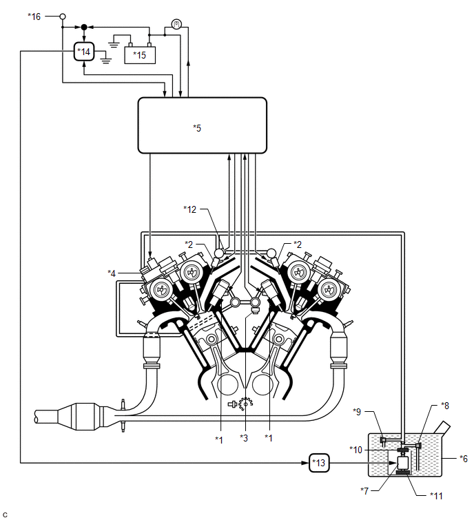
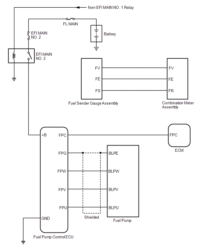
ELECTRICAL CONTROL DIAGRAM
|
*1 | Fuel Injector Assembly (for Direct Injection) |
*2 | Fuel Injector Assembly (for Port Injection) |
|
*3 | Fuel Pressure Sensor (Fuel Delivery Pipe with Sensor Assembly LH) (for High Pressure) |
*4 | Fuel Pump Assembly (for High Pressure) |
|
*5 | ECM |
*6 | Fuel Tank Assembly |
|
*7 | Fuel Pump (for Low Pressure) |
*8 | Fuel Main Valve Assembly (for Low Pressure) |
|
*9 | Fuel Main Valve Assembly (for High Pressure) |
*10 | Fuel Filter |
|
*11 | Suction Filter |
*12 | Fuel Pressure Sensor (Fuel Delivery Pipe with Sensor Assembly) (for Low Pressure) |
|
*13 | Fuel Pump Control ECU |
*14 | EFI MAIN NO. 2 Relay |
|
*15 | Battery |
*16 | Engine Switch |
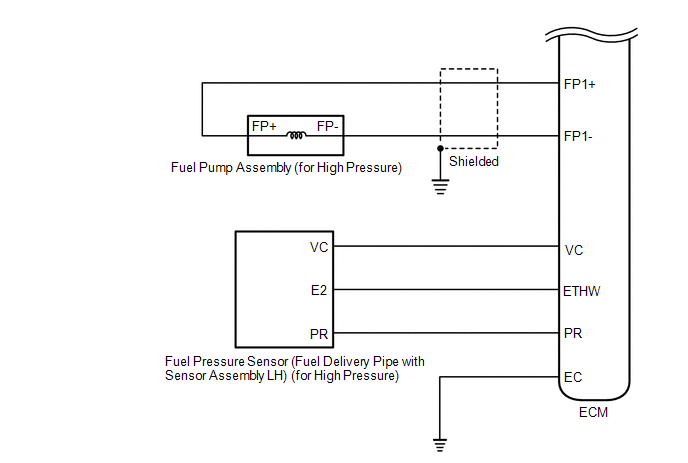
HIGH PRESSURE SIDE FUEL SYSTEM WIRING DIAGRAM

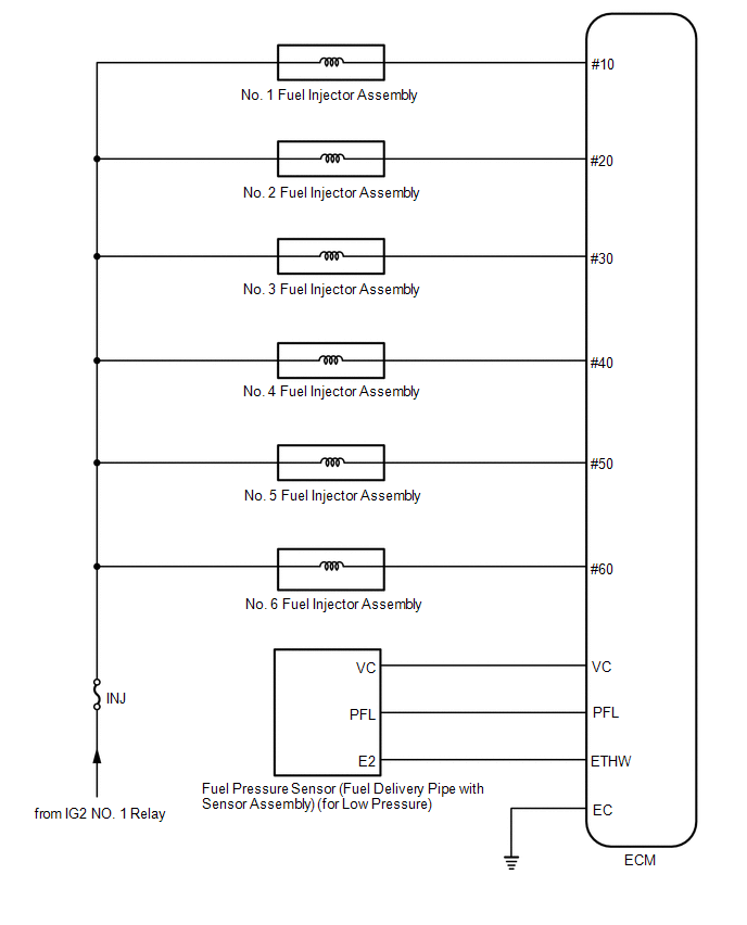
LOW PRESSURE SIDE FUEL SYSTEM WIRING DIAGRAM
READ NEXT:
 On-vehicle Inspection
ON-VEHICLE INSPECTION PROCEDURE
1. CHECK FUEL PUMP OPERATION AND INSPECT FOR FUEL LEAK (a) Check fuel pump operation.
(1) Connect the Techstream to the DLC3. (2) Turn the engine switch on (IG).
Precaution
PRECAUTION
CAUTION:
Never perform work on fuel system components near any possible ignition sources.
Vaporized fuel could ignite, resulting in a serious accident.
Do not perform work
Parts Location
PARTS LOCATION ILLUSTRATION
*1 FUEL SENDER GAUGE ASSEMBLY
*2 FUEL PUMP (for Low Pressure)
*3 FUEL PUMP CONTROL ECU
*4 FUEL TANK ASSEMBLY
*5 FUEL SUCTION
SEE MORE:
Components
COMPONENTS ILLUSTRATION
*1 REAR ARMREST ASSEMBLY
*2 REAR DOOR ARMREST COVER SUB-ASSEMBLY
*3 REAR DOOR INNER GLASS WEATHERSTRIP
*4 REAR DOOR INSIDE HANDLE SUB-ASSEMBLY
*5 REAR DOOR NO. 2 SERVICE HOLE COVER
*6 REAR DOOR TRIM BOARD SUB-ASS
Installation
INSTALLATION PROCEDURE 1. INSTALL BRAKE PEDAL PAD
(a) Install the brake pedal pad to the brake pedal support assembly. 2. INSTALL STOP LIGHT SWITCH MOUNTING ADJUSTER
(a) Engage the 2 claws to install the stop light switch mounting adjuster.
3. INSTALL BRAKE PEDAL RETURN SPRING
(a) Instal
